background image


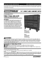
                                                                                                         Exterior Dimensions                                            Interior Dimensions                          

                 *Approx.                                  Base                                            (Roof Edge to Roof Edge)                                               (Wall to Wall)                              

                     Size                                         Size                                      Width             Depth            Height                      Width             Depth          Height                  

            12' x 10'    

   141 1/8" x 111 3/4" 

         146 1/8"        117"          103 1/4"           141 1/8"       111 3/4"        102"     


12' x 17'   

   141 1/8" x 198"      

         146 1/8"      203 1/4"     103 1/4"             141 1/8"         198"            102"  


12' x 24' 

   141 1/8" x 284 1/4"             146 1/8"      289 1/2"     103 1/4"             141 1/8"        284 1/4"       102" 


12' x 31'                141 1/8" x 370 1/2"              146 1/8"      375 3/4"     103 1/4"             141 1/8"        370 1/2"       102" 

         3,7 m x 3,0 m        358,5 cm x 283,8 cm          371,2 cm     297,2 cm     262,3 cm          358,5 cm     283,8 cm     259,1 cm

         3,7 m x 5,2 m        358,5 cm x 502,9 cm          371,2 cm     516,3 cm     262,3 cm          358,5 cm     502,9 cm     259,1 cm

         3,7 m x 7,3 m        358,5 cm x 722,0 cm          371,2 cm     735,3 cm     262,3 cm          358,5 cm     722,0 cm     259,1 cm

         3,7 m x 9,4 m        358,5 cm x 941,1 cm          371,2 cm     954,4 cm     262,3 cm          358,5 cm     941,1 cm     259,1 cm


BUILDING DIMENSIONS

CAUTION: SOME PARTS HAVE SHARP EDGES. CARE

MUST BE TAKEN WHEN HANDLING THE VARIOUS 

PIECES TO AVOID A MISHAP. FOR SAFETY SAKE, 

PLEASE READ SAFETY INFORMATION PROVIDED IN 

THIS MANUAL BEFORE BEGINNING CONSTRUCTION. 

WEAR GLOVES WHEN HANDLING METAL PARTS.

726260919

Model No.

Owner's Manual & Assembly Instructions

       BW01b

Storage Area

12'x10'

     110 Sq. Ft.     801 Cu. Ft. 

(10,2 m

2

    22,7 m

3

)


12'x17'     

194 Sq. Ft.   1419 Cu. Ft. 

(18,0 m

2

    40,2 m

3

)


12'x24'     

278 Sq. Ft.   2037 Cu. Ft. 

(25,8 m

2

    57,7 m

3

)


12'x31'     

362 Sq. Ft.   2655 Cu. Ft. 

(33,6 m

2

    75,2 m

3

)

Missing Parts, Questions on Assembly?

Call:  1-800-851-1085 or assist@arrow-

sheds.com

Do not return to dealer, they are not 

equipped to handle your requests.


Size rounded off  to the nearest foot

BGR1210FG BGR1217FG

BGR1224FG BGR1231FG

Содержание BGR1210FG

Страница 1: ...cm 722 0 cm 259 1 cm 3 7 m x 9 4 m 358 5 cm x 941 1 cm 371 2 cm 954 4 cm 262 3 cm 358 5 cm 941 1 cm 259 1 cm BUILDING DIMENSIONS CAUTION SOME PARTS HAVE SHARP EDGES CARE MUST BE TAKEN WHEN HANDLING THE VARIOUS PIECES TO AVOID A MISHAP FOR SAFETY SAKE PLEASE READ SAFETY INFORMATION PROVIDED IN THISMANUALBEFOREBEGINNINGCONSTRUCTION WEAR GLOVES WHEN HANDLING METAL PARTS 726260919 Model No Owner s Man...

Страница 2: ......

Страница 3: ...round Available by mail order or at your local dealer or you may construct a base and anchoring system of your choice Your assembly instructions provide information on a few methods commonly used to secure and level a storage building Parts and Parts List Check to be sure that you have all the necessary parts for your building All part numbers can be found on the parts All of these numbers before ...

Страница 4: ...er possible two or more people should work together to assemble your building One person can position parts or panels while the other is able to handle the fasteners and the tools Tools and Materials These are some basic tools and materials you will need for the construction of your building Decide which method of anchoring and the type of base you wish to use in order to form a complete list of t...

Страница 5: ... weight on the roof of the building When using a step ladder make sure that it is fully open and on even ground before climbing on it Keep children and pets away from worksite to avoid distractions and any accidents which may occur Do not attempt to assemble the building if parts are missing because any building left partially assembled may be seriously damaged by light winds Call 1 800 851 1085 o...

Страница 6: ...y Keep doors closed and locked to prevent wind damage Fasteners Use all washers supplied to protect against weather infiltration and to protect the metal from being scratched by screws Regularly check your building for loose screws bolts nuts etc and retighten them as necessary Moisture A plastic sheet vapor barrier placed under the entire floor area with good ventilation will reduce condensation ...

Страница 7: ...rame and lag bolt into a concrete slab Full assembly instructions and a 1 4 masonary drill bit are included TOOL HANGING RACK Model No TH100 The perfect tool organizer Twin 25 1 2 64 8 cm steel channels plus five heavy duty snap in hangers and a small tool holder for screwdrivers pliers etc Holders slide along channel for fully adjustable spacing Great for garage basement or the back of any door F...

Страница 8: ... Accessories SPECIAL NOTE If your accessory is shipped via truck line a day time phone number is required to arrange delivery If no one is available to sign for the delivery you may be subject to a re delivery charge assessed by the carrier ORDERING ACCESSORIES A08 02 13 Option 1 Accessories can be purchased through arrowsheds com Option 2 Order accessories by telephone using your MasterCard or Vi...

Страница 9: ...ill up to 4 10 2 cm in the square with gravel and tamp firm 3 Cover gravel with a sheet of 6 mil plastic 4 Construct a wood frame using four planks of 2x4 38 mm x 89 mm lumber 5 Pour in concrete to fill in the hole and the frame giving a total of 4 10 2 cm thick concrete Be sure surface is level Allow 3 5 hours for construction and a week for concrete curing time Note Before beginning construction...

Страница 10: ... instruction Anchoring into Concrete 1 For poured concrete slab or footing or patio blocks Use 1 4 x 2 6 mm x 51 mm Lag Screws 2 For Anchor Post of Concrete poured after building is erected Use 1 4 x 6 6 mm x 152 mm Lag Screws Arrow Anchoring Kit Model No AK4 or 60298 Recommended for use with any suggested base Contains 4 Anchors with Cable Clamps and installation instruction Anchoring into Wood P...

Страница 11: ...Packed with Screws 65900A 10Bx1 2 13 mm Black Screw 4 Packed with Screws 65408 10 32x1 4 6 mm Bolts 4 65989 1 4 20x1 2 13 mm Hex Head Bolt 8 Packed with Screws Hardware for Building BW11a 66098 Plastic Spacer 5 65004 8Ax5 16 8 mm Screw 403 190 Carton 4 65106 10 32 Square Nut 200 184 Carton 4 65101 1 4 20 Square Nut 12 Packed with Screws 65943 10 32x7 16 11 mm Bolt 194 184 Carton 4 67293 Weather St...

Страница 12: ...Beam 6 27 7942 Right Gable 2 28 7943 Left Gable 2 29 10460 Right Track Support 1 30 10461 Left Track Support 1 31 6372 Gable Strut 2 2 32 7827 Left Roof Panel 2 33 7826 Right Roof Panel 2 34 7828 Middle Roof Panel 4 6 35 7843 Ridge Cap 1 1 36 6874 Ridge Cap 1 37 5220 Side Roof Trim 2 2 38 6014 Side Roof Trim 2 39 7845 Left Rake 2 40 7846 Right Rake 2 41 7913 Spring Support Bracket 2 42 7830 Right ...

Страница 13: ...Assembly by Key No BW13 MAIN WALL PANEL CORNER WALL PANEL 12 ...

Страница 14: ...FF 13 Door Section with weather stripping 1 End Hinge 3 End Hinge 2 End Hinge 1 Center Hinge Door Lock Assembly Top Fixture Bottom Fixture Right Bottom Fixture Left Roller Inside Step Plate Door Section 2 2 2 3 1 3 1 1 1 1 2 10 ...

Страница 15: ...per Cable Vertical Track Flag Angle Left Flag Angle Right Snap Latch Horizontal Curve Track Right Horizontal Curve Track Left Spring Cable Safety Cable S Hook Cable Clip Pulley Clevis Track Bracket 2 2 1 1 1 2 4 1 1 2 2 2 2 2 4 2 Extension Spring ...

Страница 16: ...5 Hex Bolt with Hole 1 4 Self Drilling Screw 1 4 Sheet Metal Screw 10 24 x 5 8 Bolt 1 4 Wiz Nut 1 4 x 5 8 Track Bolt Hex Nut 3 8 x 1 1 2 Bolt Hex Nut 3 8 x 3 4 Carriage Bolt Hex Nut 1 4 Self Drilling Screw Red 2 1 42 4 8 1 2 4 14 ...

Страница 17: ...dge Trim Mounting Flange of Brackets Must Face Towards Center Of Truss Assembly IMPORTANT Square Up Half Truss 8 Square up 1 2 truss adjust and tighten 9 Make other half and square 10 Splice both halves together with splice plate and fasten center gable braces together using 3 bolts and nuts 11 Cut the 4 pieces of edge trim in half and slip over the bottom edges of gable braces This trim is a must...

Страница 18: ...zes 6381 Mid Gable Brace 4 6380 Outer Gable Brace 4 7942 Right Gable 2 7943 Left Gable 2 7912 10 32 Square Nut 10 32x7 16 11 mm Bolt 10462 Short Mounting Flange Must Face Towards Center of Gable Step 3 Parts Needed For Roof Beam Assemblies 10462 Roof Beam 2 All Sizes 7912 Roof Beam 2 12x17 3 7 m x 5 2 m 4 12x24 3 7 m x 7 3 m 6 12x31 3 7 m x 9 4 m The roof beams join the gables to the truss and sup...

Страница 19: ...e door on either side toward the rear of building Install lower door track and ramp notch toward outside using 1 4 6 mm bolts and nuts as shown See Step 12 for Rear Door Installation 2 Position floor frames as shown and fasten at each corner using 2 bolts through the bottom and nuts on top 3 Measure the floor frame diago nally When the diagonal measure ments are equal the floor frame is square 783...

Страница 20: ...1 3 7 m x 9 4 m Fasten 2 additional side frames 7914 and truss supports 7857 to side frame 7914 using the side connection Positon rear frame at rear of assembly and fasten using the rear corner connection 4 Measure the floor frame diago nally When the measurements are equal the floor frame is square 5 Select location of side door on either side toward the rear of build ing Install lower door track...

Страница 21: ...shown NOTE Be careful to install the correct panel in each position as shown 4 Double check the part numbers of the wall panels before proceeding Each screw and bolt in the wall re quires a washer Step 6 BW18 Parts Needed For Corners All Sizes 7824 Corner Wall Panel 4 7825 Front Wall Panel 2 7822 Main Wall Panel 2 7824 10 32 Square Nut 10 32x7 16 11 mm Bolt 7822 The floor frame must be square and ...

Страница 22: ...rame 1 7837 Side Frame 2 7950 Side Wall Channel 1 7949 Side Wall Channel 1 7951 Support Channel 1 10 32 Square Nut 10 32x7 16 11 mm Bolt 7835 STEP 4 STEP 2 STEP 3 STEP 1 3 Fasten side frame to the corner panels using screws Where rear frame overlaps side frame in corner fasten using 2 bolts and nuts 4 Fasten side wall channels to the corner panels using screws Fasten overlaps in corners using bolt...

Страница 23: ...asten side frame 7837 to the front corner panel using screws Fasten overlap in corner Fasten opposite end to the frame support on truss column using 2nd set of holes This will leave a gap between side frame and truss column STEP 6 For a 12x24 3 6 m x 7 2 m building repeat column procedure here Rear Frame Assembly 1 7834 Right Front Frame 1 7835 Left Front Frame 1 7917 Truss Column see below STEP 5...

Страница 24: ... Front Column 2 7834 Right Front Frame 1 7835 Left Front Frame 1 7831 Lintel 1 Rear Frame Assembly 1 7838 Side Top Angle 2 7958 Door Track 1 7835 STEP 2 5 Fasten side top angles to the corner panels using screws Fasten support column to top angle using a bolt 6 Position door slides onto the legs from the end of door track as shown in the end view 7 Position door track to the inside of side top ang...

Страница 25: ... over lap 2 1 2 6 4 cm with 2 bolts and nuts Side angles overlap front and rear frames in the corners Fasten support column to side top angle using a bolt and nut 7 Position door slides onto the legs from the end of door track as shown in the end view 8 Position door track to the inside of side top angle butted up against support column With short flange of track at bottom fasten angle to track us...

Страница 26: ...2 Main Wall Panel see below 7823 Medium Wall Panel 1 STEP 3 STEP 1 IF YOU ARE BUILDING A 12x24 3 7 m x 7 3 m Install 3 additional main wall panels on each side of the building IF YOU ARE BUILDING A 12x31 3 7 m x 9 4 m Install 6 additional main wall panels on each side of the building 7823 8Ax5 16 8 mm Screw Crimped Rib Underneath At the truss columns fasten rib with bolt washer nut before screws a...

Страница 27: ...ide down to rear frame and to support column using bolts and nuts and to wall panel using screws Fasten support column to rear frames using bolts and nuts Fold rear wall panel slightly away from column to tighten bolts and nuts 3 Position door slides onto the legs from the end of door track as shown in the end view STEP 1 7517 7560 7948 Step 13 7958 7951 8530 STEP 4 STEP 2 4 Position door track to...

Страница 28: ...l with a door jamb and fasten at top to angle middle to brace and bottom to frame using 6Ax7 8 22 mm screws and spacers Position spacer inside wall panel rib 3Fasten outer flange of door jamb to wall panel using 3 screws 4Secure the door handle lock bracket to the opposite door jamb at the middle hole with a no slot bolt Remove and reinset screws from panel STEP 4 7972 10 32x7 16 11 mm No Slot Bol...

Страница 29: ...tion Truss Assembly on build ing by sliding truss upper chords over truss columns and fasten with 6 bolts and nuts on each side IF YOU ARE BUILDING A 12x24 3 7 m x 7 3 m Install 2 trusses on truss columns IF YOU ARE BUILDING A 12x31 3 7 m x 9 4 m Install 3 trusses on truss columns Step 15 Parts Needed For Truss 12x17 12x24 12x31 3 7 m x 5 2 m 3 7 m x 7 3 m 3 7 m x 9 4 m Truss Assembly see below 10...

Страница 30: ...t the weather stripping to length 6Install single roof beams to the left side of building in the same manner Slide a roof beam assembly 10462 over center gable flange and other end over center gable braces on truss and fasten using bolts nuts 7Fasten a gable strut to the middle roof beam behind the front gable by placing tab on end of strut between the roof beams Align the tab with holes and faste...

Страница 31: ...all screws 2Install single roof beams 7912 and center gable brace to rear section in the same manner 3Fasten roof beam assembly 7912 and struts as before 4Fasten gable strut to rear of build ing 3 7 m x 5 2 m 3 7 m x 7 3 m 3 7 m x 9 4 m 8A x 5 16 8 mm Screw 10 32 x 7 16 11 mm Bolt 10 32 Square Nut NOTE For rear entry door installation only use 3 32 dia drill to clear gable holes through rear frame...

Страница 32: ...ly weather stripping along thematingedgeoftheleftandright gables as shown Cut the weather stripping to length 7Install single roof beams to the left side of building in the same manner Slide a roof beam as sembly over center gable flange and fasten 8Fasten a gable strut to the middle roof beam behind the front gable by placing tab on end of strut between the roof beams Align the tab with holes and...

Страница 33: ...the full perimeter of the floor frame Shim under with wood shingles if necessary 4Square the front of building as previously done for base 5Anchor front frame to concrete with 1 4 6 mm diameter expandable anchor bolts or other means where shown NOTE The 95 241 3 cm door opening must be held for proper door alignment Measure between the left and right track support 95 241 3 cm 95 241 3 cm Measure D...

Страница 34: ...all the left roof panel for the right side in the position shown Remove lintel support 3Temporarily install a second right roof panel loosely as shown for removal later Do not fasten left rear panel at this time NOTE If roof beam holes do not line up with the roof panel holes shift the building from left to right If this does not help your building may not be level Shim the corners until holes lin...

Страница 35: ... the tape at this time 4Install a middle roof panel on the left side of building At the top roof beam end of panels fasten 1st roof panel rib overlaps with a bolt and nut Press 2 strips over the bolt heads Save the other 2 strips for the next overlap Remember the crimped rib is always overlapped by wide rib of adjacent panel STEP 1 10 32x7 16 11 mm Bolt 8Ax5 16 8 mm Screw 10 32 Square Nut MIDDLE R...

Страница 36: ...r the crimped rib is always overlapped by wide rib of adjacent panel Repeat procedure with 2 more middle roof panels working side to side IF YOU ARE BUILDING A 12x24 3 7 m x 7 3 m Cut 12 2 5 1 cm strips There are 3 extra middle roof panels on each side of building Fasten 7th and 8th panel overlap and apply strip over head of bolt along with ridge caps IF YOU ARE BUILDING A 12x31 3 7 m x 9 4 m Cut ...

Страница 37: ...ther stripping 3Install the right and left roof panels at the rear gables Follow fastener sequence 4Position a ridge cap 7843 on the completed front roof section 5Install the second ridge cap 6874 overlapping the first ridge cap Align the holes and fasten using bolts 6Fasten the lower end of the panels to the side top angle using screws 4 STEP 2 STEP 3 STEP 5 STEP 6 STEP 8Ax5 16 8 mm Screw 10 32x7...

Страница 38: ...anels 4Install the second ridge cap 7843 overlapping the first ridge cap Align the holes and fasten using bolts 5Temporarily remove right rear roof panel Install 4 middle roof panels As each panel is fastened carefully raise 2nd ridge cap slightly away from panels for fasteners and tape 6Install the right and left roof panels at the rear gables Follow fastener sequence 7Install the third ridge cap...

Страница 39: ...roof trim Fasten rake to the center of roof panel rib using a bolt 3Fasten roof panel rib rake peak cap and ridge cap together using bolts and nuts Fasten remaining peak cap in the same manner 4Using your thumb and index finger overbend the bottom flange of the side roof trim at the corner inward enough so the right and left roof trim caps fit onto right and left corners 5Fasten rake to side trim ...

Страница 40: ... using bolts and nuts Fasten remaining peak cap in the same manner 4Using your thumb and index finger overbendthebottomflangeoftheside roof trim at the corner inward enough so the right and left roof trim caps fit onto right and left corners 5Fasten rake to side trim using a screw into roof panel 6Fasten the roof trim caps to the side trim using a screw IF YOU ARE BUILDING A 12x24 3 7 m x 7 3 m In...

Страница 41: ...ace up to the hole in the center of the door and insert a screw 3Hold the vertical door brace against the center of the inside sur face of the door and turn the screw to hold the vertical door brace and door handle brace in place Fasten to door above and below center connection using 2 screws 4Insert a second bolt in the door handle and tighten both bolts 5Put a horizontal door brace onto the top ...

Страница 42: ...ition the top of the door so that the holes in the door line up with the holes in the door slides 3 Fasten the door to the door slides using two 10Bx1 2 13 mm screws per door slide NOTE The holes in the door slides allow you to adjust the door Place the door in the middle holes Lower Door Track 10Bx1 2 13 mm Screw Horizontal Door Brace Door Adjustment Holes Allow Door to Meet Evenly Along Its Leng...

Страница 43: ...o the Bottom Section as shown 1 bottom section weather seal 1 4 sheet metal screws inside step plate Bottom Gripping Point Step Plate Kit 1 4 Sheet Metal Screw 2 Bottom Door Section 1 Look for the section with weather seal attached to it This is the bottom section Set it on table face down the face is the outside of the door ...

Страница 44: ...oor is held in the track with rollers Insert rollers into bottom fixtures and end hinges 3 1 4 Sheet Metal Screws Bottom Fixture Left 1 Center Hinge 1 End Hinge Weather Seal Roller Bottom Fixture Right Red 1 4 Self Drilling Screws Roller Carrier Hinge Number 1 End Hinge 2 Bottom Fixture Right 1 Roller 4 1 Center Hinge 1 1 4 Sheet Metal Screw 6 1 4 Self Drilling Screw Red 8 Roller Roller Roller 1 4 ...

Страница 45: ...t lock outside handle outside handle plate inside handle Drill three 1 2 holes into the section face Drill completely through the section for the middle hole 1 Install lock assembly in section 2 2 Door Section 1 Door Lock Assembly 1 10 24 x 5 8 Bolt 2 2 Section 1 2 drill ...

Страница 46: ...F You will need for this page 45 1 4 self drilling screw snap latch Snap Latch 2 Attach a snap latch assembly to each end stile using two 1 4 self drilling screws 3 1 4 self drilling screw 1 4 Self Drilling Screw 4 2 Section ...

Страница 47: ... 4 Sheet Metal Screws 2 End Hinge Fasten end hinges marked 2 to top of section on each end stile Use 2 1 4 sheet metal screws per hinge Make sure that the two slots are at top of hinge Insert a roller into each end hinge as shown Attach 1 center hinge 4 2 End Hinge 1 4 Sheet Metal Screws 1 4 Sheet Metal Screws Roller Roller 1 4 Sheet Metal Screws Roller 2 Section ...

Страница 48: ...ten end hinges marked 3 to top of section on each end stile Use 2 1 4 sheet metal screws per hinge Make sure that the two slots are at top of hinge Insert a roller into each end hinge as shown Attach 1 center hinge 1 3 End Hinge 1 4 Sheet Metal Screws 1 4 Sheet Metal Screws Roller Roller Roller Carrier Hinge Number 1 4 Sheet Metal Screws 3 Door Section 1 Roller 3 Section ...

Страница 49: ...2 1 4 x 5 8 track bolts and nuts This bracket joins the vertical and horizontal tracks as well as the angle attached to the horizontal track Leave bolts loose at this time You will adjust the track after it is installed to the jambs 2 Always place heads of bolts to inside of the track This will prevent rollers from striking bolts Flag Angle Right 1 Vertical Track 2 Flag Angle Right Right Vertical ...

Страница 50: ... Track Left Vertical Track Fasten the vertical track and flag angle assembly to the door jamb using 1 4 Bolt and Hex Nut with 1 Washer Follow the orientation as shown below Do this for both the right and left vertical tracks 3 1 4 20 Square Nut 8 1 4 20x1 2 Hex Head Bolt 1 4 20 Square Nut 1 Washers 8 1 Washer ...

Страница 51: ...o the vertical track as shown 1 Center and level bottom section in opening If there is a gap on one end at the floor then the track will not rest on the floor by the same amount Check this when vertical tracks are in place 2 You will need for this page Assemblies from Step 29 Bottom Panel Subassembly Bottom Panel Assembly ...

Страница 52: ...s 13FF 51 Stack 2 section with 2 end hinges on top of bottom 1 section while sliding rollers into vertical track 3 You will need for this page Assemblies from Step 30 2 Panel Subassembly 2 Panel Assembly Roller Vertical Track ...

Страница 53: ...17 Step 33 Insert Panels 14FF 52 1 4 Sheet Metal Screws Attach the 1 end hinges and center hinge to the 2 section with 1 4 sheet metal screws 4 You will need for this page 1 4 Sheet Metal Screw 6 ...

Страница 54: ...nels 15FF 53 Stack 3 section with 3 end hinges on top of 2 section while sliding rollers into vertical track 5 You will need for this page Roller Vertical Track Assemblies from Step 31 3 Panel Subassembly 3 Panel Assembly ...

Страница 55: ...17 Step 33 Insert Panels 16FF 54 Attach the 2 end hinges and center hinge to the 3 section with 1 4 sheet metal screws 6 You will need for this page 1 4 Sheet Metal Screws 1 4 Sheet Metal Screw 6 2 ...

Страница 56: ...hex nut right hand vertical track 1 4 x 5 8 track bolt 2 Panel Assembly Attach a snap latch keeper to each vertical track using a bolt and nut 1 1 4 x 5 8 Track Bolt Hex Nut 2 Snap Latch Keeper 2 left hand vertical track snap latch keeper 2 Panel Assembly 1 4 hex nut 1 4 x 5 8 track bolt ...

Страница 57: ... bolt Feedthecable throughtheinside handle 2 Cable 1 Threadcablethrough1 4 hexbolthole Insert the hex bolt into the snap latch Tighten with 1 4 wiz nut 3 Hex Bolt with Hole 1 1 4 Wiz Nut 1 cable left hand vertical track lug end of cable cable Insert cable through left snap latch hole Place a lug on the end of the cable to prevent it from sliding out 1 snap latch cable Inside View of Handle ...

Страница 58: ...his page 57 Right Roof Beam Attach the spring support bracket to the back of the right roof beam using two bolts and square nuts 1 Spring Support Bracket 1 7913 10 32x7 16 Bolt 2 10 32 Square Nut 2 10 32 Square Nuts 10 32x7 16 Bolt Spring Support Bracket ...

Страница 59: ...this page 58 Left Roof Beam Attach the spring support bracket to the back of the left roof beam using two bolts and square nuts 2 10 32 Square Nuts 10 32x7 16 Bolt Spring Support Bracket 10 32x7 16 Bolt 2 10 32 Square Nut 2 Spring Support Bracket 1 7913 ...

Страница 60: ...s will prevent rollers from striking bolts 3 Fasten angle attached to horizontal curve track to flag angle with 3 8 x 3 4 carriage bolt and nut Always place heads of bolts on same side as the door sections This will prevent door from striking bolts 4 Flag Angle 3 8 Nut 1 4 Nut 1 4 x 5 8 Track Bolts Vertical Track Left Horizontal Curve Track Right Horizontal Curve Track 1 3 8 x3 4 Carriage BoltandHe...

Страница 61: ...t Horizontal Curve Track to the Spring Support Bracket using a long bolt and hex nut as shown 5 Left Roof Beam 1 4 20x1 1 2 Hex Head Bolt 2 1 4 20x1 1 2 Hex Head Bolt 1 4 20 Square Nut Left Horizontal Curve Track Spring Support Bracket 1 4 20 Square Nut 2 Repeat for Right Horizontal Track 6 ...

Страница 62: ...ire another person holding the door section while attaching the fixtures and hinges Make sure adequate help is available before continuing on with the installation Have someone stack the top section on top of the other door sections and hold it there 1 Hold Section in Place Top Section Top Door Section 1 ...

Страница 63: ...put the roller as shown You may have to angle it in 3 Top Section Slide the roller through the track so it lines up with the top track Attach the top fixture to the top section using 1 4 sheet metal screws 4 1 4 Sheet Metal Screw 2 1 4 Sheet Metal Screws Top Fixture Roller Place a roller inside of a top fixture 2 Top Fixture 1 Roller 1 ...

Страница 64: ... Roller 1 Top Fixture Roller Slide the roller into the horizontal track where it is wide enough to put the roller as shown You may have to angle it in 6 Slide the roller through the track so it lines up with the top track Attach the top fixture to the top section using 1 4 sheet metal screws 7 1 4 Sheet Metal Screw 2 1 4 Sheet Metal Screws ...

Страница 65: ...17 Step 37 Insert Top Panel 26FF 64 You will need for this page 1 4 Sheet Metal Screw 6 Attach the 3 end hinges and center hinge to the top section with 1 4 sheet metal screws 8 1 4 Sheet Metal Screws 3 ...

Страница 66: ...rs in or near section joints while the door is moving Take time to study the parts and identify them Extension Springs Extension springs mount alongside the horizontal track They stretch as the door is closed and contract as the door opens This type of spring is always used in pairs one on each side of the door Both springs are the same it will not matter which one you assemble first Safety Cable E...

Страница 67: ...at this step for opposite side of door 1 3 8 Hex Nut 3 8 x 1 1 2 Bolt Pulley Clamp locking pliers to back leg of track REVERSE SIDE With a minimum of two people raise door to fully open position 2 You will need for this page Pulley 2 3 8 x 1 1 2 Bolt and Hex Nut 2 Secure the door firmly at both sides with locking pliers Connected to the track as shown 3 ...

Страница 68: ... Warning Extension springs can cause severe damage personal injury or even death if they are not properly restrained In the event of a spring failure the safety cable will prevent the spring from being propelled away from the door Pulley Clevis 3 8 x 1 1 2 Bolt Extension Spring Safety Cable You will need for this page Extension Spring 2 Pulley 2 3 8 x 1 1 2 Bolt and Hex Nut 2 Safety Cable 2 Clevis...

Страница 69: ...ch spring cable loop to bottom fixture stud and thread spring cable over pulley 7 Thread spring cable around spring pulley 8 Spring Cable Loop Spring Cable Bottom Fixture Stud Pulley Spring Pulley Safety Cable You will need for this page Spring Cable 2 ...

Страница 70: ...pring Cable Spring Cable Spring Pulley Safety Cable You will need for this page S Hook 2 Cable Clip Cable Clip 2 Stretch spring 2 3 and clip the S hook to a hole in the horizontal angle This is referred to as initial stretch and may need adjustment see end of extension spring assembly details 10 Cable Clip S Hook ...

Страница 71: ...rd must be performed in accordance with all warnings and directions as previously stated Warning Spring adjustments can only be performed when door is in fully open position and door restraints are applied to tracks With one person holding door in the fully open position carefully remove locking pliers Slowly lower door testing the balance of the springs If door does not lift off of the floor by it...

Страница 72: ... and left track supports with notched end on top facing inside building 2Fasten long flange to track support and short flange to front wall panel using screws and washers Parts Needed For Front Door Jambs All Sizes 7830 Right Door Jamb 1 7829 Left Door Jamb 1 7830 7829 71 ...

Страница 73: ... 1 Avoid nicking or scraping the coating surface inside and out 2 Use all the washers supplied In addition to protecting against weather infiltration the washers protect the metal from being scraped by the screws 3 Keep roof base perimeter and door tracks free of debris and leaves which may accumulate and retain moisture These can do double damage since they give off acid as they decay 4 Touch up ...

Отзывы: