
To learn more about AOpen XC Cube, visit us at http://xc.aopen.com.tw, http://www.aopen.com
P/N:49.EZ802.011 Doc.no:EZ855-EG-E0410A
EZ855
3
Plug the RJ45
cable into the
network jack
(recognizable by
an icon with three
tiny computers).
1
Connect the
purple keyboard
connector to the
matching purple
connector at the
rear panel. Also
connect the green
mouse connector to
the green
connector at the
rear panel.
4
Connect the
speakers' audio
cable to the light
blue speaker jack at
the rear panel. Also
insert the speakers'
power plug into a
properly grounded
AC wall socket.
5
Connect the
microphone
cable to the pink
microphone jack
at the rear
panel.
6
Depending on
the type of printer
that you have,
connect the
printer's data cable
to the blue-colored
parallel port as
shown in the
picture.
7
Connect the
power cord to
the system's
power connector
as shown.
8
Connect the
other end of the
power cord to the
AC wall socket, and
press the power
button to boot up
your system.
Easy Installation Guide
S/PDIF IN Port
Optical Device
Optical Device
Optical Device
Eject Button
Optical Device
Eject Button
Power Button
Power Button
Floppy Disk Drive
/ Card Reader
Floppy Disk Drive
/ Card Reader
USB 2.0 Ports
USB 2.0 Ports
HDD Indicator
HDD Indicator
IEEE1394 Port
(6 pin)
IEEE1394 Port
(6 pin)
IEEE1394 Port (4 pin)
IEEE1394 Port (4 pin)
Microphone Jack
Microphone Jack
S/PDIF OUT Port
S/PDIF OUT Port
Phone Jack
Phone Jack
COM1 Port
PS/2 Mouse Connector
Parallel Port
PS/2 Keyboard Connector
Monitor Connector
Coaxial Out RCA Port
Power Connector
USB 2.0 Ports
Line-Out Jack (L/R)
Line-In Jack (SUR)
Ethernet Network
Connector (RJ45)
Microphone Jack (C/B)
IEEE1394 Port (6 pin)
Voltage selector switch
(115/230V)
Power Supply Switch
2
Connect the
monitor's video
cable to the blue
monitor connector
located at the rear
panel.
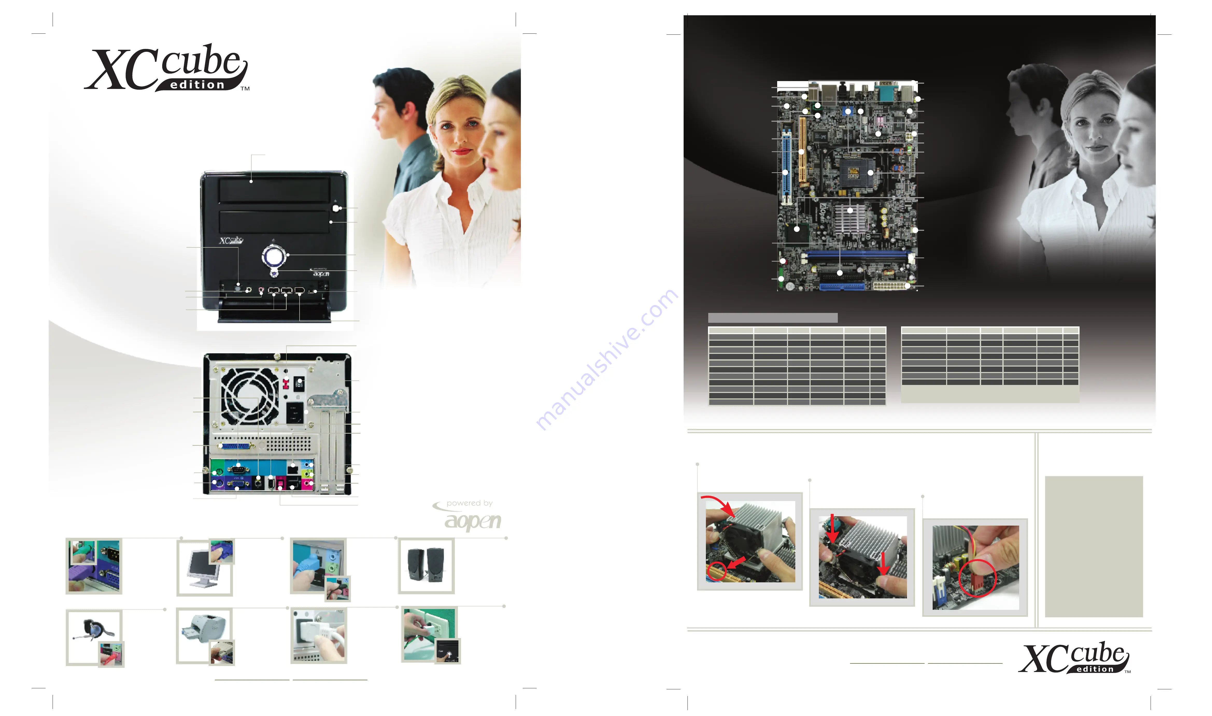
Cooler Installation
Cooler Installation
Technical
Notice
Technical
Notice
To learn more about AOpen XC Cube, visit us at http://xc.aopen.com.tw, http://www.aopen.com
P/N:49.EZ802.011 Doc.no:EZ855-EG-E0410A
UX855GME
CPU (Socket 479) Frequency Table
CPU (Socket 479) Frequency Table
4-pin ATX Power
AGP 4X
PCI slot
Front Audio
IDE Connector x 2
(ATA33/ 66/100)
JP14 CMOS
Jumper
Front Panel
Connector
AC'97 CODEC
CD_IN
AUX_IN
JP4 & JP5
AUX_IN Jumper
USB 2.0 x 4
DDR333/266/200
DIMMx 2
Max. 2 GB
ATX Power
IEEE 1394 x 2
JP28 KB/MS
Wake_up Jumper
Back Panel
CPUFAN1
Printer Connector
FDD Connector
479-pin CPU Socket
supports Intel
®
Pentium
®
M and
Celeron
®
M CPU
Intel
ICH4-M Chipset
Pentium M 755
Pentium M 745
2.0 GHz
1.8 GHz
20 x
18 x
2MB
2MB
400MHz
400MHz
100MHz
100MHz
Celeron M 360
Celeron M 350
1.4 GHz
1.3 GHz
14 x
13 x
1MB
1MB
400MHz
400MHz
100MHz
100MHz
Celeron M 340
Celeron M 330
1.5 GHz
1.4 GHz
15 x
14 x
512KB
512KB
400MHz
400MHz
100MHz
100MHz
Celeron M 320
Celeron M 310
1.3 GHz
1.2 GHz
13 x
12 x
512KB
512KB
400MHz
400MHz
100MHz
100MHz
Celeron M 353
Celeron M 333
900 MHz
900 MHz
9 x
9 x
512KB
512KB
400MHz
400MHz
100MHz
100MHz
Pentium M 735
Pentium M 725
1.7 GHz
1.6 GHz
17 x
16 x
2MB
2MB
400MHz
400MHz
100MHz
100MHz
Pentium M 715
Pentium M 705
1.5 GHz
1.5 GHz
15 x
15 x
2MB
1MB
400MHz
400MHz
100MHz
100MHz
Pentium M 738
Pentium M 718
1.4 GHz
1.3 GHz
14 x
13 x
2MB
1MB
400MHz
400MHz
100MHz
100MHz
Pentium M 733
Pentium M 723
1.1 GHz
1.0 GHz
11 x
10 x
2MB
2MB
400MHz
400MHz
100MHz
100MHz
Pentium M 713
1.1 GHz
11 x
1MB
400MHz
100MHz
Note:
With CPU changing rapidly, there might be faster CPU on the
market by the you received this installation guide. This table is
kindly for your references only.
1
Push four iron plates up a bit
and then put CPU cooler firmly
onto the CPU retention module.
Note:
For Optimized heat-
dissipating, the fan should be
placed next to the slots onboard.
*
UX855GME is based on
powerful Intel 855GME
chipset, which provides
integrated graphics
capabilty. Because i855GME
is designed for LVDS ( low
voltage differential signal
interface ) use, there will be
the possibility that the
monitor won't work properly
after powering on. If this
condition happens, please
press
< Ctrl + Alt + F1 >
concurrently to enable the
monitor after hearing the
"Welcome Effect" of the OS.
2
Press four iron plates
downward till you hear a "chip"
sound.
3
Connect the fan cable onto
the CPU FAN connector onboard.
Processor Name Clock Speed
FSB
System Bus L2 Cache Ratio
Processor Name Clock Speed
Ratio
L2 Cache
System Bus
FSB


