background image

1

OWNER’S MANUAL

UHF-EXT500

UHF PLL SYNTHESIZED

Summary of Contents for UHF-EXT500

Page 1: ...1 OWNER S MANUAL UHF EXT500 UHF PLL SYNTHESIZED ...

Page 2: ...eight carrier immediately of any damage to the shipping box or product Repack the unit in the original box and wait for inspection by the carrier s claim agent Notify your Anchor Audio authorized dealer of the pending freight claim NOTE All damage claims must be made with freight carrier RETURNING SYSTEMS FOR SERVICE OR REPAIR MESSAGE FROM ANCHOR AUDIO Congratulations on purchasing an Anchor Audio...

Page 3: ...the equipment near heat sources such as radiators heating ducts amplifier etc Do not expose the equipment to direct sunlight extreme dust excessive moisture rain mechanical vibrations or shock Take out the battery from transmitter if the appliance had been not used for a long period This will avoid the damage resulting from a defective leaking battery If the equipment is not going to be used for a...

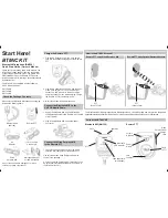
Page 4: ...3 QUICK START GUIDE Connect Receiver to Power Cable Connect Mixer or Amplifier Balanced XLR Cable Unbalanced 1 4 Phono Cable Scan Free Channel SET 2 SECONDS ...

Page 5: ...4 Insert Batteries SYNC Step 1 Step 2 or 4 SECONDS 4 SECONDS MUST BE LESS THAN 1 METER AWAY FROM Belt pack OR HANDHELD MICROPHONE PRESS AND HOLD SYNC PRESS AND HOLD SYNC SYNC ...

Page 6: ...ic level 20sB or line level 0dB 5 Squelch turn the knob to adjust or decrease the noise floor level 6 Power Adapter connector 1 MANUAL Use this mode to select free channel manually 2 SCAN Use this mode to set free channel by auto scan function 3 PRESET Use this mode to set multiple constructions by preset group 4 SYNC The synchronization process is actuated 5 GP Display selected preset group 6 CH ...

Page 7: ...he polarity of batteries is correct 8 Mini XLR Connector Connect to the lapel microphone or headset microphone 9 Gain Switch The switch sets the audio input to 20dB 10dB or 0dB 3 Talk Button Push the button up to talk 4 SYNC Button Press to actuate the synchronization process with the receiver 5 LCD Display Display channel number and battery power level 6 Battery Compartment Insert two AA dry or r...

Page 8: ... time This may cause signal loss or increased noise Set the audio output level for MIC 20dB LINE 0dB Default setting Using the Volume Knob to adjust the AF audio level to the input of the amplifier or mixer Use the SQ squelch to avoid reproducing noise when the receiver does not receive enough signal from the transmitter Turn clockwise to increase squelch and reduce noise When turning the squelch ...

Page 9: ...ep transmitter at least one meter away from receiver Setting up interference free channel by manual operation Using the button to select the MANUAL mode Press SET button for 2 seconds till LCD display is flashing Press button to change the channel forward Press SET button to lock the setting SETTING UP CHANNEL ON RECEIVER ...

Page 10: ...s SET button for 2 seconds till LCD display is flashing Press button to scan in forward direction and it will stop at the free interference channel automatically Press the SET button to lock the setting Set interference free channel by automatic frequency function ...

Page 11: ...t preset group switch to the next preset group If all 4 preset groups have interference use the auto scan mode or manual mode to set up the system Use the button to select the PRESET mode Press the channel button to change the programmable group forward Press the channel button to change the programmable channel forward Press SET button for 2 seconds till LCD display is flashing Press SET button t...

Page 12: ...the battery compartment and confirm the marks of the polarity Press for 4 seconds to turn the Handheld Belt pack transmitter on If the LED stays flashing It indicates that the battery will be out of power soon and should be replaced Adjust the audio input level 0dB default setting 10dB 20dB NOTE When you aren t using the handheld mic belt pack for a long period of time move the power switch to Off...

Page 13: ...The SYNC flashes on the receiver display panel Press the SYNC button on the receiver front panel the transmitter will set the same channel as receiver automatically 2 When using SYNC setting the distance of receiver and transmitter should be within 1 meter Step 1 USE BELT PACK OR HANDHELD MICROPHONE Step 2 PRESS AND HOLD SYNC PRESS AND HOLD SYNC SYNC MUST BE LESS THAN 1 METER AWAY FROM BELT PACK O...

Page 14: ...13 COLOR AND LABEL IDENTIFICATION You can also stick the color label on the receiver and transmitter for quickly identifying the paired system ...

Page 15: ...ifier input Check whether transmitter is too far away from receiver or SQUELCH control set too high Check whether receiver is located too near metal object or there are obstructions between transmitter and receiver Sound Interference Check the antenna location When using 2 or above microphone sets simultaneously make sure that the chosen frequencies are not interfered Check whether the interferenc...

Page 16: ...2 4 2 x 20 x 18 3 cm Weight 2 05 lbs 0 93 Kg Handheld Belt pack Transmitter Frequency Range UHF 540 570 MHz Regionally Selected Channel Select SYNC with Receiver Display LCD displays status or channel battery RF Power Output 10mW max Frequency Stability 0 005 Spurious Emission 60 dB below carrier frequency Gain Setting Belt pack 0 dB 10 dB 20 dB 3 settings Mic Unit Handheld Uni Direction dynamic u...

Page 17: ...s The apparatus should be connected to a main socket outlet with a protective earthing connection For Nordic markings refer to copy of marking label The plug in the power cord is the AC mains disconnected device and must remain readily operable There should be a minimum distance around the apparatus for sufficient ventilation The ventilation should not be impeded by covering the ventilation openin...

Page 18: ...plug is required be sure the service technician has used a replacement plug specified by the manufacturer that has the same overload protection as the original plug 15 Outdoor Antenna Grounding If an outside antenna or cable system is connected to the product be sure the antenna or cable system is grounded so as to provide some protection against voltage surges and built up static charges Article ...

Page 19: ...ed to negligent use connected to improper power sources misuse and or operation beyond specifications and limits Warranty shall not apply to exterior finish AC power cords bulbs or any other failings due to normal wear Warranty is void when equipment is subjected to adverse temperature humidity moisture or any condition not considered normal environmental conditions Products out of warranty cannot...

Reviews: