

Quick Start Guide
MXD-2000XL-PAN
20.3" Modero X Series
®
Panoramic Wall Mount Touch Panel
Overview
The MXD-2000XL-PAN 20.3" Modero X Series
®
Panoramic Wall Mount Touch Panels
feature a beautiful, panoramic capacitive multi-touch screen that provides users access to
multiple applications with minimal navigation. It is hardware-ready for support of Near Field
Communication™ (NFC) Technology to allow integration with NFC capable personal
devices. The panoramic design offers the ability to perform multiple functions simultaneously.
The MXD-2000XL-PAN is available in Portrait and Landscape layouts:
Product Specifications
Note: The MXD-2000XL-PAN-P-NC (FG5968-33) and MXD-2000XL-PAN-L-NC
(FG5968-34) No Comm touch panels do not have camera, microphone, or NFC capability.
These otherwise have all of the functionality of the MXD-2000XL-PAN panels.
MXD-2000XL-PAN Installation
•
For more detailed installation instructions including important notes on thermal
concerns with Rack and Wall installations, refer to the
X-Series Touch Panels MXD/T-
2000-XL-PAN & MXD/T-1900 -PAN Instruction Manual
(available to view/download
from www.amx.com).
•
Detailed specifications drawings for the MXD-2000XL-PAN are available to download
from www.amx.com.
The MXD-2000XL-PAN may be installed directly into a solid surface environment, using
either solid surface screws or the included locking tabs for different mounting options.
Once installed, the panel is contained within a clear outer housing known as the Backbox.
The Backbox is removed to install it into a wall, or when using the optional Rough-In Box
accessory (
FG039-15
).
Note: For typical mounting surfaces, such as drywall, use the locking tabs as the primary
method for securing the Backbox to the surface. For thin walls or solid surfaces, use
mounting screws (not included).
Installing the MXD-2000XL-PAN Into a Wall
The MXD-2000XL-PAN comes with a clear plastic Backbox (FIG. 2) designed to attach the
panel to most standard wall materials. This Backbox has four locking tabs (2 on top, 2 on
bottom) to help lock the Backbox to the wall.
These locking tabs are only extended AFTER the Backbox is inserted into the wall.
•
When installing the Backbox, make sure that the assembly is in the correct position
and in the correct place. Once the locking tabs are extended and locked into place,
removing the Backbox may be difficult without having access to the back of the wall or
causing damage to the wall.
•
In order to ensure a stable installation of the MXD-2000XL-PAN, the thickness of the
wall material must be a minimum of .50 inches (1.27cm) and a maximum of .875
inches (2.22cm). The mounting surface should also be smooth and flat.
The Backbox also has four slots for accepting the temporary mounting posts mounted on
the back of the device.
Installing the Backbox
Since the cutout for the Backbox is off-center from the edges of the touch panel, use the
included Installation Template (
68-5968-01
) to ensure proper placement. The template is
marked on one side with directions for both landscape and portrait installations to ensure that
the touch panel and Backbox are properly aligned.
WARNING: Using the Installation template to select the final placement of the Backbox is
highly recommended. The outside edges of the template are the same dimensions as the
touch panel, which allows you to troubleshoot possible conflicts with wall edges, doors, and
other potential obstacles.
1. Prepare the area by removing any screws or nails from the drywall before beginning the
cutout process.
2. After ensuring proper placement, cut out the mounting surface for the Backbox, using the
(included) Installation Template as a guide.
CAUTION: Making sure that the actual cutout opening is slightly smaller than the pro-
vided dimensions is highly recommended. This provides a margin of error if the opening
needs to be expanded. Too little wall material removed is always better than too much.
3. Thread the incoming power and Ethernet wiring from their terminal locations through the
surface opening (see FIG. 4 on reverse).
Leave enough slack in the wiring to accommodate any re-positioning of the panel.
4. Remove any knockouts as needed on either long dimension of the Backbox to facilitate
incoming wiring and pull the wiring through the resultant holes.
5. Push the Backbox into the wall opening. Insure that the locking tabs lie flush against the
Backbox.
6. Extend the locking tabs on the sides of the Backbox by tightening the screws inside the
box until snug. Apply enough pressure to the screw head to keep the box flush with the
wall: this ensures that the locking tabs will tighten up against the inside of the wall.
7. For additional strength, #4 mounting screws (not included) may be secured through the
mounting holes located at the left and right sides of the panel (FIG. 4).
In order to prevent damage to the touch panel, make sure that these are flush with the
Backbox.
8. Insert each connector into its corresponding location along the back of the device.
9. Test the incoming wiring by attaching the panel connections to their terminal locations
and applying power. Verify that the panel is receiving power and functioning properly to
prevent repetition of the installation.
Remove power before continuing with the installation.
Note: Do not disconnect the cables from the touch panel. The panel must be installed
with the cables attached before being inserted into the drywall.
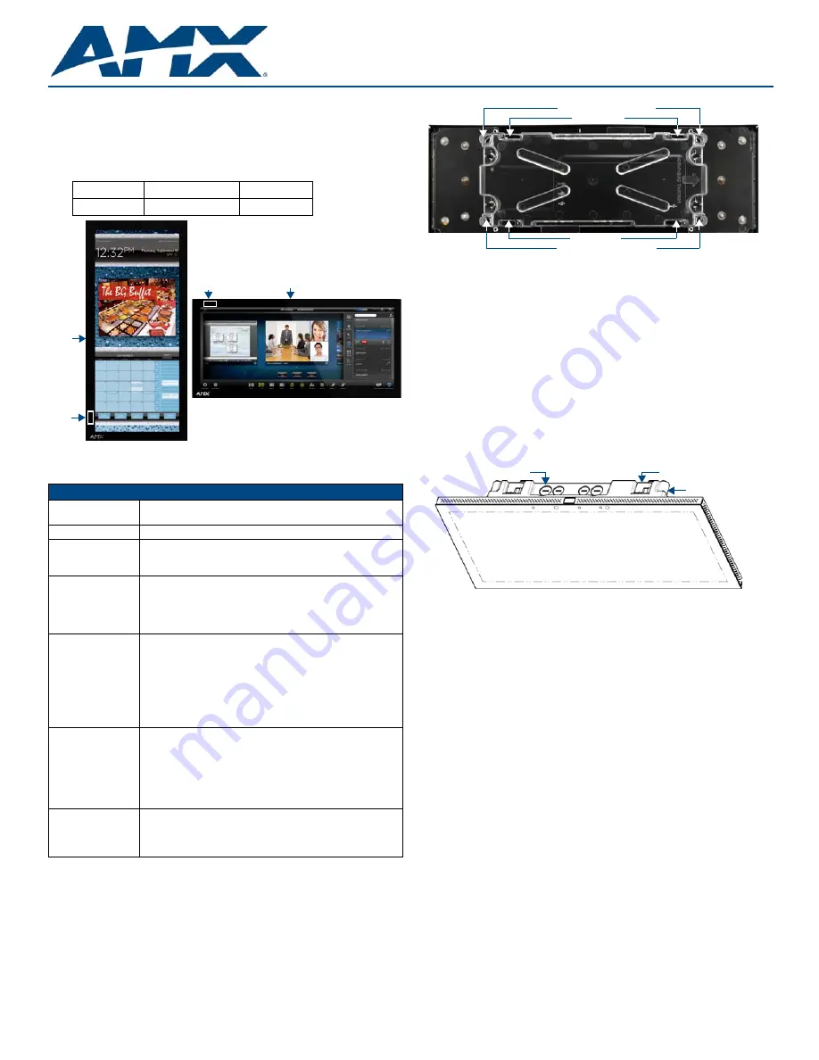
Portrait
MXD-2000XL-PAN-P
FG5968-05
Landscape
MXD-2000XL-PAN-L
FG5968-11
FIG. 1
MXD-2000XL-PAN-P/L (Portrait and Landscape)
MXD-2000XL-PAN Specifications
Dimensions (HWD)
• Landscape: 9 1/2" x 20 3/8" x 11/16" (242mm x 519mm x 19mm)
• Portrait: 20 3/8" x 9 1/2" x 11/16" (519mm x 242mm x 19mm)
Weight
9.1 lbs (4.13 Kg)
Power Consumption
• Full-On: 32W (12 VDC, 2.7 A)
• Standby: 3.10 W (12 VDC, 0.3 A)
• Start-Up Inrush Current: 4.0 A for 80 µsec
External Power
Supply Required
Requires one of these AMX power sources (not included):
• PSN4.4 Power Supply, 4.4 A, 3.5 mm Phoenix, 13.5 VDC
(FG423-45)
• MXA-MPL Modero X Series Multi Preview Live (FG5968-10)
• MXA-MP Modero X Series Multi Preview (FG5968-20)
Certifications
• UL 60950-1
• FCC Part 15 Class B
• C-Tick CISPR 22 Class B
• CE EN 55022, EN 55024 and EN 60950-1
• IEC 60950-1
• IC
• IEC/EN-60950
• RoHS/WEEE compliant
Environmental
• Temperature (Operating): 32° F to 104° F (0° C to 40° C)
• Temperature (Storage): 4° F to 140° F (-20° C to 60° C)
• Humidity (Operating): 20% to 85% RH
• Humidity (Storage): 5% to 85% RH
• Power ("Heat") Dissipation:
On: 109.2 BTU/hr
Standby: 10.6 BTU/hr
Included Accessories
• Locking 2-pin Phoenix mate (41-0002-SA)
• MXA-USB-C, USB Port Cover Kit (FG5968-18)
• MXA-CLK, Modero X Series Cleaning Kit (FG5968-16)
• Installation Template 20.3" (68-5968-01)
Sleep Button
NFC Sensor
Sleep
NFC
Button
Sensor
MXD-2000XL-PAN-P
MXD-2000XL-PAN-L
FIG. 2
MXD-2000XL-PAN Backbox
FIG. 3
MXD-2000XL-PAN (Landscape)
Locking Tabs
Locking Tabs
Temporary Mounting Posts
Temporary Mounting Posts
Backbox
Backbox knockouts (X8)
Locking tabs (X4)


