

Installation Guide
MAX MMS-04S
MultiMedia Server
MAX MMS-04S Multimedia Server
The MAX MMS-04S Multimedia Server (FIG. 1) utilizes a RAID5 disk drive system to
keep an ever expanding library of DVDs and CDs well organized, simple to access,
and easy to use. The MMS-04S server features a robust internal hard drive system
that allows you to efficiently manage hundreds of DVDs and CDs.
The MMS-04S accommodates single and multi-room video distribution, allowing the
user to search and select chapters, titles and tracks. Video is stored in native DVD
format to fully capture the quality of the original video. Music is stored in native audio
CD format (although the MMS provides playback of MP3 files as well).
•
The MMS-04S supports up to 25 MAX-AVM audio/video modules, via ethernet.
•
The MMS-04S supports up to 2 MAX-AOM audio-only modules, via USB.
Product Specifications
Initial Setup and Configuration
The following sections describe the basic process of setting up the MMS server and
making the configurations required to get the server up and running with one or more
MAX-AVM and/or MAX-AOM modules.
Follow the directions outlined below, and refer to FIG 1 for the location and orientation
of the connectors mentioned in these steps.
Use the WinMAX software to add/remove content on the MMS server, and control
playback. Additional documentation, including the
WinMAX Software Instruction
Manual
and the
MAX by AMX Reference Guide
are available online at www.amx.com.
Note
: Static electricity can damage electronic circuitry. Before touching the MMS,
discharge any accumulated static electricity from your body by touching a grounded
metal object.
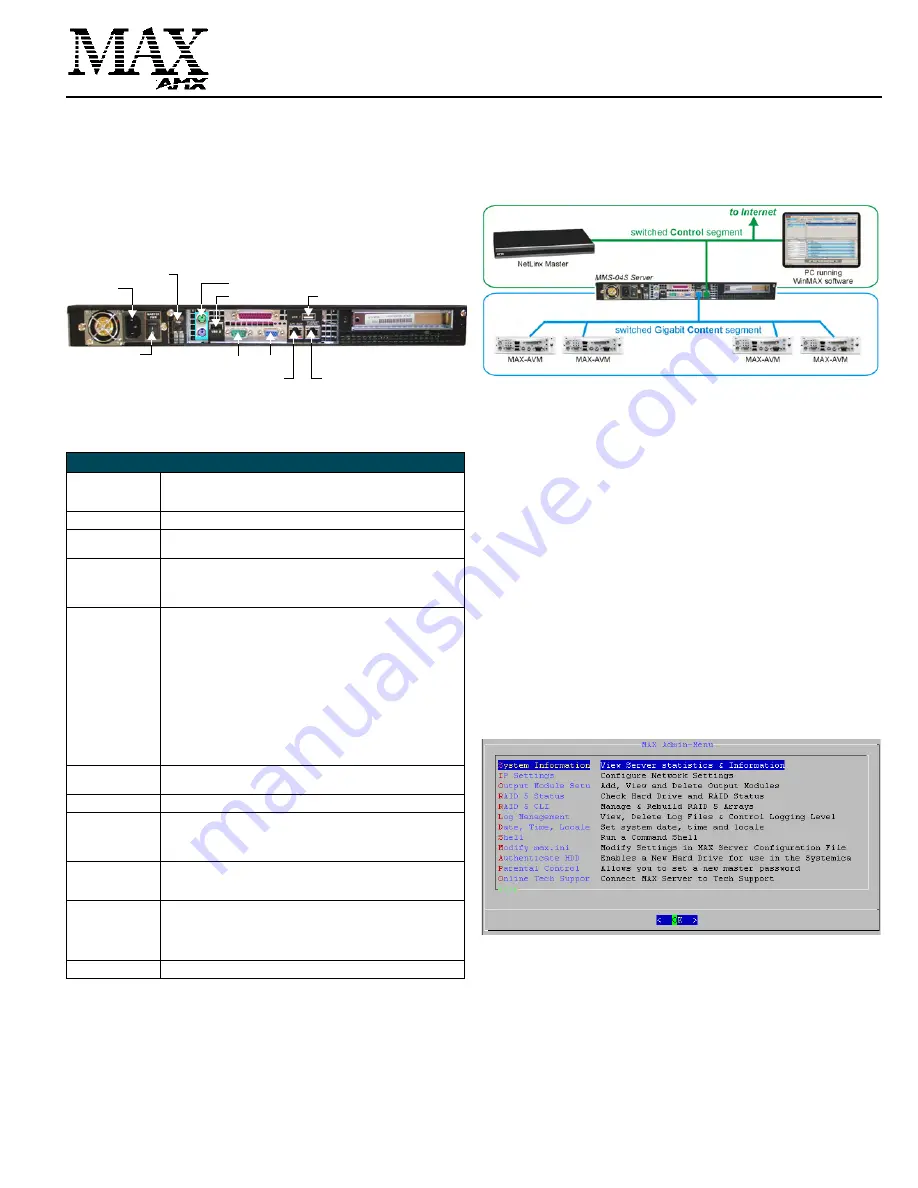
Network Segment Layout for MMS Servers
It is required that the
control
segment of the network is kept separated from the
(switched)
content delivery
segment, as indicated in FIG. 2.
Step 1: Connect a Mouse, Keyboard and VGA Monitor
Connect a PS/2 mouse and keyboard, and a VGA monitor directly to the MMS server
to access the on-board interface, called the
MAX Admin Menu
(FIG. 3)
.
You’ll use the
options in the Admin Menu to configure communication settings and add/remove
MAX-AVM and MAX-AOM modules.
Note
: Alternatively, you can access the MAX Admin Menu via Telnet, using the Server
Configuration feature in the WInMAX software. This requires that the MMS server is
configured with an IP address and Subnet Mask settings which are appropriate for
your network configuration. Refer to “Step 7: Install and Configure WinMAX Software”
for details.
Step 2: Connect the Power Cables and Apply Power
Note
: Consider using a UPS with the MMS server, modules and ethernet switch (if
applicable).
1.
Connect both of the power supplies, using the supplied power cords.
2.
Push the Power On/Off pushbutton to apply power.
3.
Allow up to one minute for the MMS server to boot-up.
Shutting Down the MMS Server
Always shut down the MMS server is via the
Shutdown
command in the
MAX Admin
Menu
. This allows the operating system to shut down completely before power is
removed, and prevents the time-consuming reinitialization process that results from an
improper shut down (and cannot be cancelled).
Step 3: Access the MAX Admin Menu
Once the boot-up process is complete, the MAX Admin Menu (FIG. 3) is displayed:
Working With the MAX Admin Menu
•
Use the arrow keys on the keyboard to highlight the desired option, and press
Enter to make a selection. Do not use the arrow keys on your keyboard’s numeric
keypad.
•
Beyond this menu, press the TAB button to navigate through the elements on the
pages until an asterisk appears next to the desired selection.
•
Press the spacebar to make a selection (press again to de-select).
FIG. 1
MMS-04S MultiMedia Server (rear view)
MMS-04S (FG 2178-07) Specifications
Storage capacity:
• 1 terabyte of storage space
• 100 DVD (2,500 CD) capacity (approximate values)
• Approximately 25 CDs can be stored in place of 1 DVD
Power:
110-240 VAC, 50/60Hz
AC Current Draw
(AMP):
• 1.55A - Bootup/Power Cycle Peak
• 1.15A - Normal Usage Peak
Front Panel
Components:
(remove Faceplate to
access)
• 4 hot-swappable 250GB hard drives
• DVD/CDRW drive
• Drive Status LEDs
• Ventilated front cover
Rear Panel
Components:
• Power Cable connector: IEC connector for AC power cable (included)
• Master Power Supply switch: Turns the power supply on/off
• Power On/Off button: Turns the MMS on/off
• PS/2 Keyboard and Mouse ports
• USB ports 1 & 2: Type A USB connectors connect to MAX-AOM
module(s) for audio distribution
• RS-232 port: DB-9 serial port for external control
• Parallel port:
not used
• VGA port: DB15HD port provides VGA output
• ETHERNET CONTROL port: RJ-45 Gigabit Ethernet port provides
1000/100/10 Mb/s network connectivity between the MMS and the
NetLinx Master or PC
• A/V OUT port: RJ-45 Gigabit Ethernet port provides 1000/100/10 Mb/s
network connectivity between the MMS and MAX-AVM module(s) for
A/V distribution
Dimensions (HWD):
(without rack ears)
• 1.75”" x 17.3" x 20" (4.45 cm x 43.94 cm x 50.80 cm)
• 1 RU (mounts in a standard 19” equipment rack)
Weight:
42 lbs (19.05 kg)
Operating
Environment:
• Operating Temperature: 10º to 35º C
• Operating Relative Humidity: 20% to 80% (non-condensing)
• Minimum Ventilation Clearance: 3" front and 3" rear
• Operating acoustic noise: 62 dBA
Included
Accessories:
• One 6’ (1.83m) power cable
• One DVD, one CD
• Rack-mounting kit
Other AMX/MAX
Products:
• MAX-AVM Audio-Video Module
(FG 2178-50)
• MAX-AOM Audio-Only (USB) Module
(FG 2178-55)
• MAX-AOM-EX Expansion Kit (
FG 2178-56
)
• MAX-MDL200 Multi-Disc Loader
(FG 2179-01)
• MMS-HDD250G Replacement 250MB HDD
(FG 2178-250)
Certification:
UL Listed E252362, FCC, CE
Power On/Off pushbutton
Power cable
connector
PS/2 keyboard & mouse ports
RS-232
VGA
USB 2
port
A/V OUT
USB 1
port
Master Power
ETHERNET CONTROL
switched GB
Control
segment
(to NetLinx Master or PC)
switched GB
Content
segment
(to MAX-AVM Modules)
switch
FIG. 2
Network Segment Layout
FIG. 3
MAX Admin Menu


