

Installation Guide
Distributed Audio
LCD Keypads
Overview
The Matrix Audio Controller LCD Keypads (FIG. 1) are compatible with both Delta and
Mi Series Audio Controller Systems and provide Direct Access Control and advanced
functionality such as:
•
Setting and recalling Source Presets
•
Setting and recalling Source Favorites
•
Zone Grouping
•
Alarm clock settings
•
Keypad Lockout
DAS-KP-LCD-G Flush Mount LCD Keypad (FG1120-0X)
The DAS-KP-LCD-G Flush Mount LCD Keypad combines the control functionality of
the DAS-KP-4e/KP-6e and DAS-KP-NUM keypads, with the added benefit of visual
feedback.
The DAS-KP-LCD-G is available in the following colors:
•
Gloss Black (FG1120-01)
•
Gloss White (FG1120-02)
•
Gloss Almond (FG1120-03)
•
Gloss Ivory (FG1120-04)
DAS-KP-LCDS-W Surface Mount LCD Keypad (FG1120-12)
The DAS-KP-LCDS-W Surface Mount (retrofit) LCD Keypad combines the control
functionality of the DAS-KP-4e-G/KP-6e-G and DAS-KP-NUM-G keypads, with the
added benefit of visual feedback.
•
The Surface Mount LCD Keypad fits into a standard single gang box.
•
The DAS-KP-LCDS-W is available in Matte White
LCD Keypads - Features By Model
The following table indicates the features supported by each of the Matrix Audio
Controller Keypads:
Installing the Surface-Mount LCD Keypad (DAS-KP-LCDS-W)
The DAS-KP-LCDS-W Surface Mount LCD Keypad is shipped completely assembled.
To correctly install the DAS-KP-LCDS-W (
retrofit
) in the wall, you must remove the
Front Bezel and the LCD screen.
Please follow these instructions carefully to ensure correct installation and operation.
Note
: Before installing the LCD Keypads, POWER OFF the Matrix Controller (and
Expansion Controllers, if applicable).
1.
To remove the Front Bezel, firmly hold the rear connector board with one hand
while squeezing the top and bottom near one edge of the front bezel with the
other hand. While squeezing, gently pull the bezel back and down. A soft click
should be heard when the bezel is freed from the mounting plate.
2.
Use a small Phillips screwdriver to remove the four screws in the corners of the
LCD board. Once all the screws have been removed, gently grip each side of the
LCD screen and rock it away from the mounting plate. This will slowly release
the LCD screen from the bank of pins connecting it to the Keypad Control Board.
3.
Plug the speaker-wire connectors to the “To Speakers” connector and plug the
Zone wires into the “To Controller” connector on the back of the Keypad Connec-
tor Board. Ensure the wiring scheme is correct and that the connector at the
Controller is plugged into the Zone output.
4.
Use the provided screws to mount the Keypad Mounting Plate to the j-box in the
wall. Make sure the screws are secure enough that the keypad will not move
when touched but be sure not to overtighten the screws. If the screws are over-
tightened, the connection between the LCD Screen and the Keypad Control
board may not be adequate.
5.
Reconnect the LCD screen to the Keypad Control board making sure to line up
the four screw holes correctly. This will ensure that all the pins will be plugged
into their appropriate receptacles.
6.
Secure the LCD screen with the four screws that were removed in step #2.
Make sure the volume buttons are still in place on the switches.
7.
Before placing the Front Bezel over the screen, POWER ON the Controller (and
Expansion Controllers, if applicable). The DAS-KP-LCDS-W will start the initial-
ization process immediately.
Note
: When the System is first powered ON, it could take up to 2 minutes to load all
the information to the LCD keypads. Please wait until initialization has completed
before using the keypad.
8.
If everything initialized correctly you should see the source listing at the top of
the screen and “All-On”, “All-Off” and the time displayed at the bottom of the
screen.
9.
Remove the protective film from the front of the LCD Touch-screen.
10.
Place the Front Bezel on the LCD screen and firmly “click” it into place. It should
fit tightly to the Mounting plate.
Installing the Flush-Mount LCD Keypad (DAS-KP-LCD-G)
The DAS-KP-LCD-G Flush Mount LCD Keypad is shipped completely assembled.
Note
: Before installing the LCD Keypads, POWER OFF the Matrix Controller (and
Expansion Controllers, if applicable).
1.
Using the cut-out template provided, center the template on the desired location
on the wall and mark the hole to be cut.
2.
Connect the appropriate speaker & controller cables to the back of the
DAS-KP-LCD-G.
•
The speaker connector is located on the right-hand side
•
The controller connector is located on the left-hand side.
3.
Remove the bezel from the front, and insert the LCD Keypad and housing into
the hole in the wall.
4.
Press the housing firmly against the wall and tighten the 4 mounting screws
(black Phillips head) located in each corner of the housing. This will cause the
doglegs to extend and press against the drywall and will secure the Keypad to
the drywall. Be sure not to over-tighten these screws.
5.
Remove the protective film from the front of the LCD Touch-screen.
6.
Carefully place the keypad bezel on the front of the Keypad.
Start on one side making sure the volume button fits through the appropriate vol-
ume hole, and gently squeeze the cover to secure it to the other side of the
housing. The second volume button may need to be pressed in order to fit
through the appropriate volume hole.
7.
POWER ON the controller (and Expansion Controllers, if applicable). The
DAS-KP-LCD-G will start the initialization process immediately.
Note
: When the System is first powered ON, it could take up to 2 minutes to load all
the information to the LCD keypads. Please wait until initialization has completed
before using the keypad.
8.
If everything initialized correctly you should see the source listing at the top of
the screen and “
All-On
”, “
All-Off
” and the
time
displayed at the bottom of the
screen.
9.
To remove the cover, gently pry from the top corner until all four clips release
from the housing.
Using the Keypads
Matrix DAS-KP LCD keypads have a unique, touch-sensitive LCD panel that has 12
individual “grids” (also called “touch fields”) that become different command buttons
depending on what source and previous command was selected.
Labeling the Keypad Grids
The Matrix touch panel keypads provide the ability to customize the following labels in
the grids (also called “touch fields 1-12” - see FIG. 2):
•
Source Names (from the Controller)
•
IR command labels (from the Controller)
The above customized field labels are stored on the Mi Series Controller so that it can
be shared with other LCD keypads, the Network Interface application, or anything
using RS-232 commands to control the Mi Series Controller.
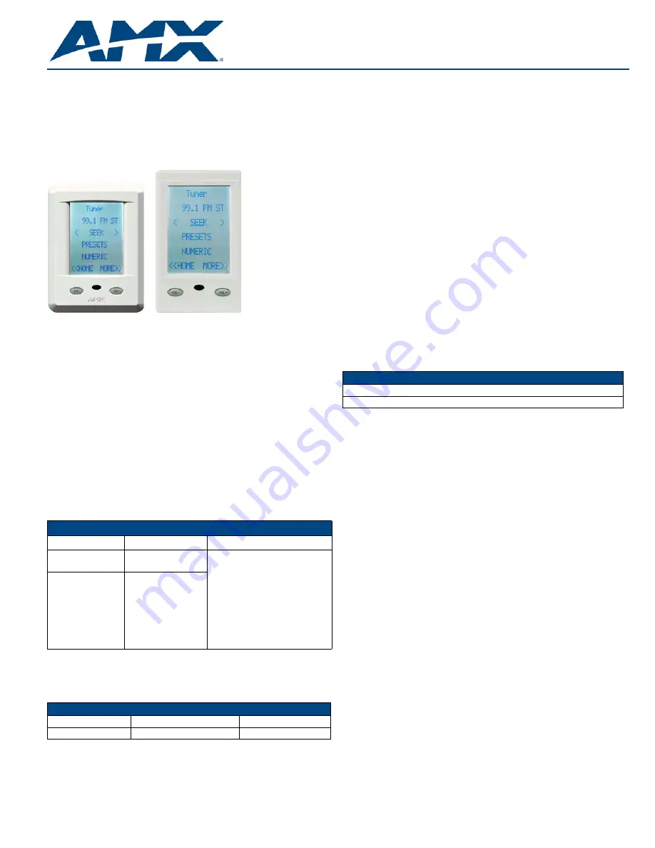
FIG. 1
Matrix Audio Controller LCD Keypads
LCD Keypads - Features By Model
Model Name
Description
Features
•
DAS-KP-LCD-G
(FG1120-0X)
Flush Mount LCD
Keypad
• Control of up to 8 sources
• Direct access control
• Setting/recalling presets
• Setting/recalling favorites
• Zone grouping
• Bass, treble, balance and SRS
control
• Alarm clock settings
• Keypad lockout
• Built-in IR receiver
• 4-pin input/output connectors
•
DAS-KP-LCDS-W
(FG1120-12)
Surface Mount LCD
Keypad
Parts List
• Front Bezel
• Keypad Control Board
• Mounting Plate
• LCD Touch-screen
• Keypad Connector Board
• Mounting Screws x 2
DAS-KP-LCDS-W
Surface Mount LCD Keypad
DAS-KP-LCD-G
Flush Mount LCD Keypad
Parts List
• Front Bezel
• LCD Touch-screen & Housing


