Amtran VO370M_LGD, Service Manual
The Amtran VO370M_LGD Service Manual is a comprehensive user manual essential for maximizing your product experience. Available for free download, this manual provides detailed instructions and troubleshooting solutions, ensuring seamless operation and optimal performance. Enhance your device usage with this invaluable resource available at manualshive.com.
Share
Download


Reviews:
No comments
Related manuals for VO370M_LGD
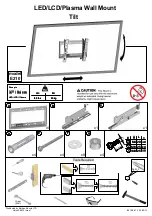
E210
Brand: Barkan Pages: 34

43
Brand: Barkan Pages: 8

PF400
Brand: Kanto Pages: 16
PH-50HU31S
Brand: XOCECO Pages: 32

7761-K461
Brand: NCR Pages: 8

DA110CD
Brand: August Pages: 17

CTV 577 VT
Brand: Clatronic Pages: 12

21LAS1
Brand: akira Pages: 37

TE43551B42V2K
Brand: Telefunken Pages: 80
S5400A Series
Brand: TCL Pages: 19

19SV07
Brand: SV2000 Pages: 16

CTV-5040
Brand: Audiovox Pages: 12

QSL322T
Brand: SONIQ Pages: 32

P745 98P745K
Brand: TCL Pages: 17

FLP43T354
Brand: Hyundai Pages: 104

H25E37Y
Brand: Zenith Pages: 40

PT3235SB
Brand: Palsonic Pages: 25

42LW5700
Brand: Samsung Pages: 108


