AML Oceanographic AML-1 RT, User Manual
The AML Oceanographic AML-1 RT comes with a comprehensive User Manual, available for free download on our website. This manual is a valuable resource, providing step-by-step instructions and helpful insights on using and maintaining your AML-1 RT device. Visit manualshive.com to download your copy today and unlock the full potential of this exceptional product.
Share
Download


Reviews:
No comments
Related manuals for AML-1 RT

24950
Brand: Oemtools Pages: 4

P100
Brand: idiag Pages: 10

2290
Brand: Bandit Pages: 136

Versaflo S Series
Brand: 3M Pages: 11

DBI Sala EXOFIT
Brand: 3M Pages: 32

746
Brand: 3M Pages: 8

WS Series
Brand: Accurate Bio-Medical Technology Pages: 35

FES-200 W3
Brand: Abicor Binzel Pages: 92

ORPscan10
Brand: Bante Instruments Pages: 6

A8
Brand: JB-Lighting Pages: 40
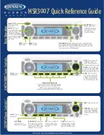
MSR3007
Brand: Jensen Pages: 2
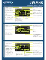
JWM45
Brand: Jensen Pages: 2

MC-174CRM
Brand: Maeda Pages: 276

TissueLyser II
Brand: Qiagen Pages: 48

QIAcube
Brand: Qiagen Pages: 162

44083
Brand: Qazqa Pages: 4

QWCD35
Brand: Qlightec Pages: 12

US-428
Brand: Tascam Pages: 78


