background image

©Copyright AMKUS Rescue Systems 2020-2021

1

LAP-012 October 7, 2021 Rev02

AMKUS RESCUE SYSTEMS

AMKUS.com 

4201 Montdale Drive, Valparaiso, IN 46383-4098 USA

800-592-6587 · 219-548-5000

G-Force

INSTRUCTIONS FOR INSTALLATION, OPERATION, AND MAINTENANCE
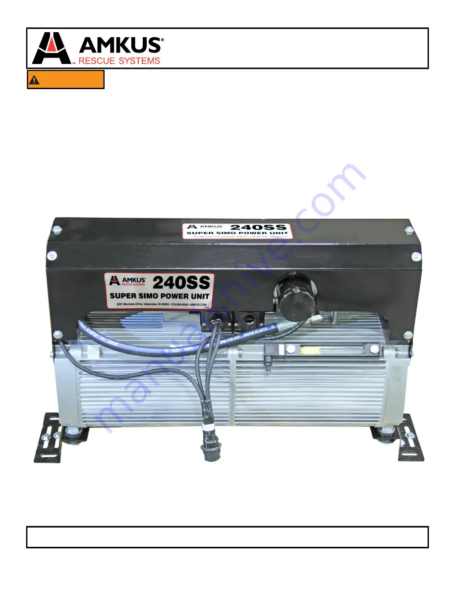
240SS

Super Simo Power Unit

WARNING

Understand manual before use. Operating AMKUS Rescue Systems without understanding the 

manual, receiving proper training, and using appropriate personal protective equipment is a misuse 

of AMKUS equipment. Obtain safety information at amkus.com 
This instruction manual is intended to familiarize operators and maintenance personnel with the

operation, basic maintenance, and safety procedures associated with this product. This manual 

should be kept available to all operating and maintenance personnel. 
This manual does NOT address servicing of AMKUS Rescue Systems. Only competent rescue tool 

repair technicians are qualified to repair AMKUS equipment. 
This manual is intended for use with manuals published by manufacturers of the prime movers

(motor and pump) used in this power unit.

Summary of Contents for Super Simo 240SS

Page 1: ...al protective equipment is a misuse of AMKUS equipment Obtain safety information at amkus com This instruction manual is intended to familiarize operators and maintenance personnel with the operation basic maintenance and safety procedures associated with this product This manual should be kept available to all operating and maintenance personnel This manual does NOT address servicing of AMKUS Res...

Page 2: ...SPONSIBILITY to know that you have been properly trained in Firefighting and or Emergency Response and in the use precautions and care of any equipment you may be called upon to use 4 IT IS YOUR RESPONSIBILITY to be in proper physical condition and to maintain the personal skill level required to operate any equipment you may be called upon to use 5 IT IS YOUR RESPONSIBILITY to know that your equip...

Page 3: ... n I l l i p S Health Information Recommend use of the chemical and restrictions on use l i o c i l u a r d y H e s U d e d n e m m o c e R SECTION 2 HAZARDS IDENTIFICATION 6 ODVVL cation Not a hazardous substance or mixture GHS Label element d e r i u q e r l o b m y s d r a z a h o N s m a r g o t c i p d r a z a H d r o w l a n g i s o N d r o w l a n g i S S D R A Z A H L A C I S Y H P s t n e...

Page 4: ...ING THE UNIT 7 2 3 FILLING THE UNIT 7 2 4 CONNECTING THE PRESSURE AND RETURN HOSES 7 2 5 HEAT EXCHANGER 7 2 6 CONTROL PANEL 7 2 7 VFD PANEL 7 2 8 WIRELESS REMOTE CONTROLS OPTIONAL 8 0 INITIAL START UP 9 0 OPERATION 9 1 GENERAL 9 2 OPTIONAL WIRELESS REMOTE CONTROL 9 2 1 FEATURES 9 2 2 OPERATING INSTRUCTIONS 10 0 TROUBLESHOOTING GUIDE 11 0 ROUTINE MAINTENANCE 11 1 HYDRAULIC PUMP 11 1 1 OIL CHANGE PR...

Page 5: ...ep covers and guards in place and in working order WARNING Using rescue tools can cause ignition or explosion resulting in injury or death Ignition or explosion can result from situations such as Flammable hazards are created when fuel lines refrigerant lines atomized oil or pressurized hydraulic fluid lines are breached Ignition sources can suddenly ignite these fuels Flammable vapors can be rele...

Page 6: ...pect and properly maintain rescue equipment Inspect all rescue equipment after each use Any equipment found damaged or inoperable should be removed from service Storage of rescue equipment in adverse conditions Always store rescue equipment in clean dry and secure conditions Operation of rescue equipment with missing or illegible safety markings Modification of tools and power units inconsistent w...

Page 7: ...e location providing master on off switch circuit controls low oil high temperature indicator lights The Human Machine Interface HMI display provides system operational information as well as input and output indicators to quickly troubleshoot the system An Ethernet interface provides a programming and troubleshooting connection for factory assistance should the need occur to interface to the powe...

Page 8: ... 7 2021 Rev02 4 1 PART IDENTIFICATION Figure 4 1 Power Unit Wireless Remote Controls Receiver Reel Return Reel Pressure Reel Return Reel Pressure Sight Gauge Drain Plug Vent Cap Reservoir Fill Cap Oil Filter Heat Exchanger Inlet Power Plug Heat Exchanger Outlet ...

Page 9: ...een or the button switches below the user may Start the system Operate either pump motor Open or close the pump valves See Section 9 0 on page 17 for detailed operating instructions I O Screen The I O screen shows the states of each input and output in real time This screen is most helpful for troubleshooting a system Runtime Screen The runtime screen shows total hours of use on each motor ...

Page 10: ...tober 7 2021 Rev02 4 3 WIRING IDENTIFICATION Figure 4 3 Connection Callouts 1 Radio TR 2 HMI Ethernet C5 3 HMI POWER CONTROL HMI 4 OIL TEMP SENSORS LVTEMP 5 12VDC IN 12 IN 6 12VDC OUT 12 OUT 7 MOTOR 1 M1 8 MOTOR 2 M2 9 208 240VAC IN POWER 1 2 3 4 5 6 7 8 9 ...

Page 11: ... Copyright AMKUS Rescue Systems 2020 2021 11 LAP 012 October 7 2021 Rev02 5 0 OVERALL DIMENSIONS Figure 5 0 ...

Page 12: ... optional remote control system A VFD Variable Frequency Drive Panel B Control Panel C Heat Exchanger D Power Unit Figure 7 2A WARNING Tool operators bear responsibility for ensuring use of appropriate protective clothing and equipment The chosen protective clothing and equipment must provide protection from potential hazards users may encounter while operating AMKUS rescue tools Requirements for ...

Page 13: ...being used be sure the pressure line has a male coupler at the end of the reel The return line will have a female coupler at the end of the reel If AMKUS Mono Couplers are being used be sure the pressure line is connected to the pressure port P of the female Mono Coupler and the return line is connected to the tank port T of the female Mono Coupler Figure 7 2 4 NOTICE Use of hydraulic fluids other...

Page 14: ... control button Refer to the operating section of this manual for further explanation of button functions Mount the 240SS Control Panel in a compartment accessible to operators 7 2 7 VFD PANEL Mount the 240SS VFD Panel in a compartment Ensure the VFD can be accessed and the cover can be easily removed by maintenance technicians 7 2 8 WIRELESS REMOTE CONTROLS OPTIONAL 1 Mount the reciever in a comp...

Page 15: ...N position by flipping each switch up 4 The upper section of the Control Panel houses the touch screen display and the touch display The green button is used to enable disable the entire unit Press the physical or digital green button to start the system The screen should indicate the system has started ON 5 Press the physical or digital blue M1 button to start Motor No 1 The screen should indicat...

Page 16: ...id level continues to drop after several minutes check for fluid leaks 10 When finished shut the power unit off 11 Replenish hydraulic fluid until the sight gauge is completely full Pressure Line Fluid Flowing From The Pressure Line Return Line 12 To verify the pressure and return hoses remove both couplings from the end of the hoses and place the hose ends in a bucket 13 Charge the appropriate va...

Page 17: ... to turn control valve off 9 2 2 OPERATING INSTRUCTIONS 1 Rotate the Emergency Stop 1 Red thumb wheel clockwise and release to ensure the remote is in the operation mode 2 Press and hold both start buttons at the bottom of the remote While holding the start buttons the remote is linking up to the receiver mounted in the apparatus Hold the start buttons pressed firmly to ensure a good signal 3 Push...

Page 18: ...e hydraulic fluid to drain completely 5 Clean and reinstall the drain plug 6 Replace the filter 7 Fill the hydraulic fluid reservoir with new AMKUS MV1 fluid 8 Reinstall the fill plug vent cap 9 Cycle rescue tools several times to purge air from the hydraulic hoses 11 2 HYDRAULIC HOSES After each use hoses should be wiped clean with a light cleaner such as Simple Green Inspect hoses for damage to ...

Page 19: ...een remaining dark after the unit is powered on and running Figure 11 4 1 Flip the PLC Run Stop switch to the Stop position 2 Power down the PLC completely 3 Use an insulated screw driver to pull out the battery holder from the PLC 4 Remove and replace battery with a quality BR2032 coin battery or equivalent Be sure the battery polarity is correct positive is indicated 5 Slide the battery holder i...

Page 20: ...tool hoses fittings and couplings clean see routine maintenance for hoses and couplings 3 If the power unit becomes contaminated determine the nature of the contamination Follow the decontamination guidelines provided by the Authority Having Jurisdiction Technical advice may be requested from AMKUS Rescue Systems 4 Inspect the power unit hoses fittings and couplings after each use for damage leaka...

Reviews: