


Operating Manual
AMAZONE
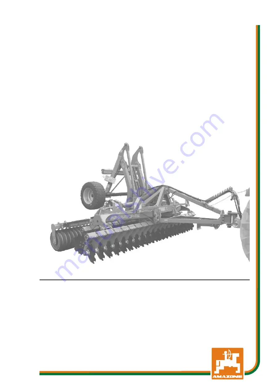
Catros 4001-2TS
Catros
+
4001-2TS
Catros 5001-2TS
Catros
+
5001-2TS
Catros 6001-2TS
Catros
+
6001-2TS
Compact Disc Cultivator
MG3661
BAG0081.10 09.14
Printed in Germany
Please read and follow this
operating manual before putting
the machine into operation.
Keep it in a safe place for
future use.
en
Summary of Contents for Catros 4001-2TS
Page 89: ......


