Alware Senrigan-GP-45, Instruction Manual
The Alware Senrigan-GP-45 is a cutting-edge GPS device designed for outdoor enthusiasts. Never get lost again with its accuracy and reliability. To learn how to maximize its features, make sure to download the free Instruction Manual from manualshive.com. Get yours today and start exploring with confidence.
Share
Download


Reviews:
No comments
Related manuals for Senrigan-GP-45

331340 1907
Brand: DELTA-SPORT Pages: 15
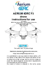
F3
Brand: 4DRC Pages: 19

QQ190 FALCON
Brand: QuadQuestions Pages: 12

14139
Brand: Apex Digital Pages: 19

LOKI X3
Brand: Storm Pages: 20

Angle 120 AHP+
Brand: Jamara Pages: 16

NGDRONE2G
Brand: National Geographic Pages: 12

500B Camera Edition
Brand: iSwag Pages: 8

518785
Brand: Air Wars Pages: 6

F11 4K PRO
Brand: SJRC Pages: 25

SOKAR FPV DRONE
Brand: Skyrc Pages: 2

OSPERY
Brand: Skyrc Pages: 12

ZAP 400 V2
Brand: RCmart Pages: 20

Flanker W606-5
Brand: HJ Toys Pages: 9


