Allis-Chalmers LA-600, Instruction Book
The Allis-Chalmers LA-600 Instruction Book is a comprehensive manual providing detailed guidance on how to use and maintain this impressive product. With step-by-step instructions and valuable insights, this manual is available for free download on manualshive.com. Easily access it to enhance your experience with the LA-600.
Share
Download


Reviews:
No comments
Related manuals for LA-600

GRD9L-R
Brand: GEYA Pages: 4

DC-GFP 100
Brand: MidNite Solar Pages: 4

NH2-125
Brand: CHINT Pages: 6

Crouse-Hinds GFSX1
Brand: Eaton Pages: 4

Power Defense PD3
Brand: Eaton Pages: 9

Westinghouse DB-100
Brand: NATIONAL SWITCHGEAR Pages: 42

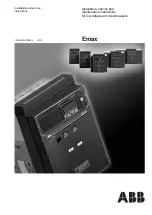
Emax E1.2
Brand: ABB Pages: 109
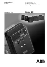
Emax DC L3447
Brand: ABB Pages: 112
E1B 08
Brand: ABB Pages: 161

ADVAC 38
Brand: ABB Pages: 56

8146/5-V27 Series
Brand: Stahl Pages: 60
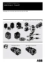
SACE Emax 2
Brand: ABB Pages: 10

ND Series
Brand: Eaton Pages: 12

EP 071
Brand: hager Pages: 2

Perun AB
Brand: Perun Airsoft Pages: 10


