STINGRAY Instruction Leaflet
V2.2.0
2
STINGRAY Instruction Leaflet
V2.2.0
3
STINGRAY Instruction Leaflet
V2.2.0
4
CE conformity
Technical and ordering info
Info
L
•
AVT STINGRAY cameras are in conformity with the CE standard
and its underlying directions.
•
Board level models are delivered without housing. Because
housing design is critical to the electromagnetic interference
characteristics of a camera, no CE certification tests regarding
electromagnetic interference have been performed for board
level models. Users who design board level models into their
systems should perform appropriate testing regarding electro-
magnetic interference after the product design is completed.
Info
L
•
Technical information:
phone (for Germany): +49 (0)36428 677-270
phone (for USA): +1 978-225-2030
outside Germany/USA: Please check the link for your local
dealer.
http://www.alliedvisiontec.com/partner.html
•
Ordering and commercial information:
phone (for Germany): +49 (0)36428 677-230
phone (for USA): +1 978-225-2030
outside Germany/USA: Please check the link for your local
dealer.
http://www.alliedvisiontec.com/partner.html
Please note order number/text given in the following tables.
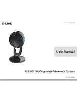
Scope of delivery
Each camera package consists of the following system components:
AVT Stingray camera
5 m cable with screw lock-
ing
Color version:
Hoya C-5000 IR cut filter
(built-in)
B/w version:
Standard glass, no filter
(built-in)
CD with driver
and documentation
Optional:
tripod adapter
Optional: GOF cable
Optional: HIROSE
connector for cable mount
HR10A-10P-12S
Figure 1: System components
www
Ý
For more accessories visit the AVT website at:
http://www.alliedvisiontec.com/avt-products/accessories.html
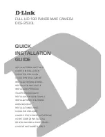
Camera I/O connector
For maximum voltage levels see
Hardware Installation Guide
, Chapter
STINGRAY
input descriptions.
Figure 2: Camera I/O connector pin assignment
Pin
Signal
Direction Level
Description
1
External GND
GND for RS232 and ext.
power
External Ground for RS232
and external power
2
External Power
+8...+36 V DC
Power supply
3
Camera Out 4
Out
Open emitter
Camera Output 4
(GPOut4)
default: -
4
Camera In 1
In
U
in
(high) = 3 V...24 V
U
in
(low) = 0 V...1.5 V
Camera Input 1
(GPIn1)
default: Trigger
5
Camera Out 3
Out
Open emitter
Camera Output 3
(GPOut3)
default: Busy
6
Camera Out 1
Out
Open emitter
Camera Output 1
(GPOut1)
default: IntEna
7
Camera In GND
In
Common GND for inputs Camera Common Input Ground
(In GND)
8
RxD RS232
In
RS232
Terminal Receive Data
9
TxD RS232
Out
RS232
Terminal Transmit Data
10
Camera Out Power In
Common VCC for outputs
max. 36 V DC
Camera Output Power
for digital outputs (OutVCC)
11
Camera In 2
In
U
in
(high) = 3 V...24 V
U
in
(low) = 0 V...1.5 V
Camera Input 2
(GPIn2)
default: -
12
Camera Out 2
Out
Open emitter
Camera Output 2
(GPOut2)
default: -
Table 1: Camera I/O connector pinning
1
10
2
9
8
7
6
12
11
3
4
5
Instruction Leaflet
V2.2.0
15 August 2008
Allied Vision Technologies GmbH
Taschenweg 2a
D-07646 Stadtroda / Germany
AVT Stingray