Allied Vision Alvium G1, User Manual
The Allied Vision Alvium G1 user manual is a comprehensive guide to help you maximize the functionality of your camera. Available for free download from manualshive.com, this manual offers detailed instructions and valuable insights to ensure a seamless experience with your Alvium G1, empowering you to capture extraordinary images.
Share
Download


Reviews:
No comments
Related manuals for Alvium G1

P1
Brand: EasyN Pages: 11

DMC-SZ5K
Brand: Panasonic Pages: 32

DMC-LZ40
Brand: Panasonic Pages: 2

DMC-GH3KBODY
Brand: Panasonic Pages: 104

DMC-FX35A - Lumix Digital Camera
Brand: Panasonic Pages: 32

DMC-SZ7K
Brand: Panasonic Pages: 23

Loop
Brand: California Labs Pages: 8

98379
Brand: Sakar Pages: 31

IntelliSHOT
Brand: VADDIO Pages: 13
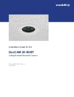
DocCAM 20 HDBT
Brand: VADDIO Pages: 5
DocCAM 20 HDBT
Brand: VADDIO Pages: 18

ClearSHOT 10 USB
Brand: VADDIO Pages: 62

RoboSHOT 12
Brand: VADDIO Pages: 41
Z3Pro
Brand: Z-EDGE Pages: 40

NVR 400
Brand: Braun Pages: 44

EXILIM EX-Z27
Brand: Casio Pages: 142

MAT EM
Brand: Yashica Pages: 13

VP220-3
Brand: VideoProtects Pages: 10


