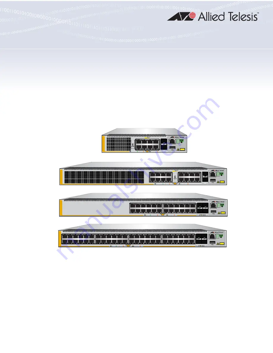
background image

613-002706 Rev. G

x530L Series

Stackable Gigabit Layer 3+ Ethernet Switches

AlliedWare Plus™ v5.5.0-2

x530L-10GHXm
x530L-18GHXm
x530L-28GPX
x530L-28GTX
x530L-52GPX
x530L-52GTX

Installation Guide for Virtual Chassis 

Stacking

A

T-x530L-10GHXm

10/S2

CLASS 1

LASER PRODUCT

CONSOLE

9/S1  

5G/2.5G/1G LINK

ACT

100 LINK

ACT

PD ON

PD ERR

MAX CURRENT

1

7

2

8

SFP+

PORTS 

9-10

SFP+

10G

/

1G

3

5

1

7

9

11

13

15

17/S1

18/S2

SFP+

16

14

CLASS 1

LASER PRODUCT

CONSOLE

4

6

8

10

12

2

A

T-x530L-18GHXm

PD ON

PD ERR

MAX CURRENT

5G/2.5G/1G LINK

ACT

100 LINK

ACT

PORTS 

17-18 
SFP+

10G

/

1G

3

5

1

7

9

11

13

15

17

19

21

23

27/S1

28/S2

25

SFP+

26

16

18

20

14

10G

/

1G

CLASS 1

LASER PRODUCT

CONSOLE

4

6

8

10

12

2

22

24

FDX

HDX           COL

A

T-x530L-28GTX

1G LINK

ACT

100 LINK

ACT

51/S1

52/S2

49

SFP+

50

3

5

1

7

9

11

13

15

17

19

21

23

4

6

8

10

12

2

16

18

20

14

22

24

27

29

25

31

33

35

37

39

41

43

45

47

28

30

32

34

36

26

40

42

44

38

46

48

CLASS 1

LASER PRODUCT

CONSOLE

10G

/

1G

A

T-x530L-52GTX

FDX

HDX           COL

1G LINK

ACT

100 LINK

ACT

Summary of Contents for x530L Series

Page 1: ... 15 17 S1 18 S2 SFP 16 14 CLASS 1 LASER PRODUCT CONSOLE 4 6 8 10 12 2 AT x530L 18GHXm PD ON PD ERR MAX CURRENT 5G 2 5G 1G LINK ACT 100 LINK ACT PORTS 17 18 SFP 10G 1G 3 5 1 7 9 11 13 15 17 19 21 23 27 S1 28 S2 25 SFP 26 16 18 20 14 10G 1G CLASS 1 LASER PRODUCT CONSOLE 4 6 8 10 12 2 22 24 FDX HDX COL AT x530L 28GTX 1G LINK ACT 100 LINK ACT 51 S1 52 S2 49 SFP 50 3 5 1 7 9 11 13 15 17 19 21 23 4 6 8 ...

Page 2: ...eir respective owners Allied Telesis Inc reserves the right to make changes in specifications and other information contained in this document without prior written notice The information provided herein is subject to change without notice In no event shall Allied Telesis Inc be liable for any incidental special indirect or consequential damages whatsoever including but not limited to lost profits...

Page 3: ...ses and can radiate radio frequency energy and if not installed and used in accordance with this instruction manual may cause harmful interference to radio communications Operation of this equipment in a residential area is likely to cause harmful interference in which case the user will be required to correct the interference at his own expense Note Modifications or changes not expressly approved...

Page 4: ...d into multiple languages in the Translated Safety Statements document at www alliedtelesis com library Remarque Les consignes de sécurité portant le symbole sont traduites dans plusieurs langues dans le document Translated Safety Statements disponible à l adresse www alliedtelesis com library ...

Page 5: ...r Over Ethernet 44 PoE Standards 44 Powered Device Classes 45 Power Budget 45 Port Prioritization 46 Wiring Implementation 47 SFP Transceiver Ports 48 1Gbps 10 Gbps SFP or SFP Transceivers 48 LEDs 48 eco friendly Button 50 VCStack Feature 51 Switch ID LED 52 USB Port 54 Console Port 55 Power Supply 56 Pre Installed AC Power Supply 56 Software and Hardware Releases 57 Chapter 2 Virtual Chassis Stac...

Page 6: ...stalling the x530L 10GHXm Switch in an Equipment Rack with the RKMT J15 Bracket 117 Required Items 117 Installing the Switch 117 Installing the x530L 18GHXm x530L 28GTX x530L 28GPX x530L 52GTX or x530L 52GPX Switch in an Equipment Rack 123 Required Items 123 Switch Orientations in the Equipment Rack 123 Installing the Switch 124 Chapter 6 Installing the Switch on a Wall 127 Switch Orientations on ...

Page 7: ... 18GHXm Switch 177 Configuring the Master x530L 18GHXm Switch Part I 178 Configuring the Master x530L 18GHXm Switch Part II 181 Verifying the Master x530L 18GHXm Switch 183 What to Do Next 186 Chapter 9 Cabling the Networking Ports 187 Cabling Twisted Pair Ports 188 Guidelines to Handling SFP and SFP Transceivers 189 Installing SFP or SFP Transceivers in the Switches 190 Installing SP10TW Direct C...

Page 8: ...Contents 8 ...

Page 9: ...ck Trunks Using Ports 25 to 28 70 Figure 26 Valid Stack Trunks Using a Combination of Ports 25 to 28 and Ports 49 to 52 71 Figure 27 Valid Stack Trunks Using a Combination of Ports 7 to 10 and Ports 15 to 18 72 Figure 28 Valid 10Gbps Stack Trunk with Both Fiber Optic and SP10TW Direct Connect Cables 73 Figure 29 Trunks of 5Gbps Ports for Stacks of Two x530L 10GHXm Switches 75 Figure 30 Trunks of 5...

Page 10: ...Installing the Plywood Base to the Wall 134 Figure 73 Installing Two Brackets on the x530L 28GTX or x530L 52GTX Switch 136 Figure 74 Installing Four Brackets on the x530L 10GHXm x530L 18GHXm x530L 28GPX and x530L 52GPX Switches 137 Figure 75 Securing the x530L 28GTX or x530L 52GTX Switch to the Plywood Base 138 Figure 76 Securing the x530L 10GHXm x530L 18GHXm x530L 28GPX or x530L 52GPX Switch to t...

Page 11: ...ts 56 Table 16 Stacking Worksheet 79 Table 17 Stacking Worksheet Columns 80 Table 18 Adding Ports 25 and 26 to the Stack Trunk on the x530L 28GPX or x530L 28GTX Switch 146 Table 19 Adding Ports 49 and 50 to the Stack Trunk on the x530L 52GPX or x530L 52GTX Switch 148 Table 20 Configuring the Master x530L 10GHXm Switch for 5Gbps Stacking Ports Part I 159 Table 21 Configuring the Master x530L 10GHXm...

Page 12: ...Tables 12 ...

Page 13: ...e contains the following sections Document Conventions on page 14 Contacting Allied Telesis on page 15 Note This guide explains how to install switches as a stack with Virtual Chassis Stacking VCStack For instructions on how to install the devices as stand alone switches refer to the x530L Series Installation Guide for Stand alone Switches ...

Page 14: ...ntions Note Notes provide additional information Caution Cautions inform you that performing or omitting a specific action may result in equipment damage or loss of data Warning Warnings inform you that performing or omitting a specific action may result in bodily injury ...

Page 15: ...upport tickets learn about Return Merchandise Authorizations RMAs and contact Allied Telesis technical experts Software Downloads Download the latest software releases for your product Licensing Register and obtain your License key to activate your product Product Documents View the most recent installation guides user guides software release notes white papers and data sheets for your product War...

Page 16: ...Preface 16 ...

Page 17: ...ge 46 eco friendly Button on page 48 VCStack Feature on page 49 Switch ID LED on page 50 USB Port on page 52 Console Port on page 53 Power Supply on page 54 Software and Hardware Releases on page 55 Note This guide explains how to install switches as a stack with Virtual Chassis Stacking VCStack For instructions on how to install the devices as stand alone switches refer to the x530L Series Instal...

Page 18: ...Transceiver Ports 9 10 1Gbps SFP 10Gbps SFP 1 2 5 5Gbps POE Ports 1 8 3 5 1 7 9 11 13 15 17 S1 18 S2 SFP 16 14 CLASS 1 LASER PRODUCT CONSOLE 4 6 8 10 12 2 AT x530L 18GHXm PD ON PD ERR MAX CURRENT 5G 2 5G 1G LINK ACT 100 LINK ACT PORTS 17 18 SFP 10G 1G 100Mbps Ports 1 16 Management Panel Transceiver Ports 17 18 1Gbps SFP 10Gbps SFP 1 2 5 5Gbps POE Ports 1 16 3 5 1 7 9 11 13 15 17 19 21 23 27 S1 28 ...

Page 19: ... 5 1 7 9 11 13 15 17 19 21 23 4 6 8 10 12 2 16 18 20 14 22 24 27 29 25 31 33 35 37 39 41 43 45 47 28 30 32 34 36 26 40 42 44 38 46 48 CLASS 1 LASER PRODUCT CONSOLE 10G 1G AT x530L 52GTX FDX HDX COL 1G LINK ACT 100 LINK ACT Ports 1 48 Management Panel Transceiver Ports 49 52 1Gbps SFP 10Gbps SFP 10Mbps 100Mbps 1Gbps 51 S1 52 S2 49 SFP 50 3 5 1 7 9 11 13 15 17 19 21 23 4 6 8 10 12 2 16 18 20 14 22 2...

Page 20: ... 8 x530L 18GHXm Back Panel Figure 9 x530L 52GPX and x530L 28GPX Back Panel Figure 10 x530L 52GTX and x530L 28GTX Back Panel AC Power Supply Connector AC Power Supply Connector 100 240 VAC 100 240 VAC PSU 2 PSU 1 4586 AC Power Supply Connector AC Power Supply Connector 100 240VAC 4587 100 240VAC PSU 2 PSU 1 AC Power Supply Connector AC Power Supply Connector ...

Page 21: ...r Virtual Chassis Stacking 21 Management Panel Figure 11 identifies the components on the management panel Figure 11 Management Panel CLASS 1 LASER PRODUCT CONSOLE 4567 Console eco friendly Button USB Port Switch ID LED Management Port ...

Page 22: ... X at 100Mbps and 1 2 5 5Gbps Port Link Activity L A and Duplex Collision D C LEDs The twisted pair ports on the AT x530L 28GTX 1 to 24 and AT x530L 52GTX 1 to 48 switches have these features Supports 10Mbps 100Mbps and 1 Gbps operation 100 meters 328 feet maximum operating distance per port Auto Negotiation for speed Table 1 Basic Features Feature x530L 10GHXm PoE x530L 18GHXm PoE x530L 28GTX x53...

Page 23: ...The twisted pair ports on the AT x530L 52GPX 1 to 48 switch have these features Ports 1 to 40 support 10 100Mbps and 1 Gbps operation Ports 41 to 48 support 100Mbps and 1 2 5 5Gbps operation 100 meters 328 feet maximum operating distance per port Auto Negotiation for speed Full duplex mode only MDI MDI X at 10 100Mbps Power over Ethernet PoE supported on all 48 ports Port Link Activity L A and Pow...

Page 24: ...8 powered devices PoE 90 watts maximum for 5 powered devices Supports powered device classes 0 to 8 Port prioritization Mode wiring Classes 0 4 Type 1 or 2 up to 30W Mode A MDI x Classes 5 6 Type 3 up to 45W 60W Mode A MDI x plus Mode B MDI x MDI Classes 7 8 Type 4 up to 75W 90W Mode A MDI x plus Mode B MDI x MDI IEEE802 3af at bt compliant The basic features of PoE on the twisted pair ports on th...

Page 25: ...kilometers Examples of SFP 10Gbps transceivers include SP10SR LR ER and ZR series of short or long distance transceivers using multi mode or single mode fiber optic cable SP10TW series of direct attach cables in lengths of 1 meter and 3 meters SP10T transceiver with RJ 45 connector for links up to 20 meters at 10Gbps with Category 6a or better twisted pair cable or 100 meters at 1Gbps SP10LRM Long...

Page 26: ...L 52GTX switches Switch ID number LED Installation Options The installation options are Desk or tabletop 19 inch equipment rack Wood or concrete wall Management Software and Interfaces The management software and interfaces are AlliedWare Plus Management Software Command line interface CLI Management Methods The following methods are used for managing the switches Local management through the Cons...

Page 27: ...o Negotiation only The default is Auto Negotiation for all ports Duplex Mode Ports 1 8 100Mbps Full or half duplex mode 1 2 5 5Gbps Full duplex mode only Supports Auto Negotiation at 100Mbps Maximum Distance 100 meters 328 feet Power over Ethernet PoE 15 4W maximum per port 8 PDs PoE 30W maximum per port 8 PDs PoE 60W maximum per port 8 PDs PoE 90W maximum per port 5 PDs Maximum Power Budget 500W ...

Page 28: ...rts 1 16 100Mbps Full or half duplex mode 1 2 5 5Gbps Full duplex mode only Supports Auto Negotiation at 100Mbps Maximum Distance 100 meters 328 feet Power over Ethernet PoE 15 4W maximum per port 16 PDs PoE 30W maximum per port 16 PDs PoE 60W maximum per port 12 PDs PoE 90W maximum per port 8 PDs Maximum Power Budget 720W PoE Mode Classes 0 4 Type 1 or 2 up to 30W Mode A MDI x Classes 5 6 Type 3 ...

Page 29: ...0Mbps or 1 Gbps 10Mbps 100Mbps Set the port speed manually or with Auto Negotiation 1Gbps The port speed is set with Auto Negotiation only The default is Auto Negotiation for all ports Duplex Mode Ports 1 24 10Mbps 100Mbps Full or half duplex mode 1Gbps Full duplex mode only Supports Auto Negotiation at 10Mbps and 100Mbps Maximum Distance 100 meters 328 feet Connector 8 pin RJ 45 ...

Page 30: ...speed is set with Auto Negotiation only The default is Auto Negotiation for all ports Duplex Mode Ports 1 24 10Mbps 100Mbps Full or half duplex mode 1Gbps Full duplex mode only Supports Auto Negotiation at 10Mbps and 100Mbps Maximum Distance 100 meters 328 feet Power over Ethernet PoE 15 4W maximum per port and PoE 30W maximum per port Maximum Power Budget 740W 370W per power supply PoE Mode Class...

Page 31: ...00Mbps or 1Gbps 10Mbps 100Mbps Set the port speed manually or with Auto Negotiation 1Gbps The port speed is set with Auto Negotiation only The default is Auto Negotiation for all ports Duplex Mode Ports 1 48 10Mbps 100Mbps Full or half duplex mode 1Gbps Full duplex mode only Supports Auto Negotiation at 10Mbps and 100Mbps Maximum Distance 100 meters 328 feet Connector 8 pin RJ 45 ...

Page 32: ...eed is set manually while its duplex mode is established through Auto Negotiation Table 7 x530L 52GPX Switch Twisted Pair Port Specifications Specification Description Port Speed Ports 1 48 10Mbps 100Mbps or 1Gbps 10Mbps 100Mbps Set the port speed manually or with Auto Negotiation 1Gbps The port speed is set with Auto Negotiation only The default is Auto Negotiation for all ports Duplex Mode Ports...

Page 33: ... and the other MDI X For example a switch port must be set to MDI X if it is connected to a network device set to MDI The wiring configurations of the ports can be set manually or automatically by the switch with auto MDI MDI X IEEE 802 3ab compliant This feature enables the switch to automatically negotiate with network devices to establish their proper settings The MDI and MDI X settings do not ...

Page 34: ...PoE LED Table 8 x530L 10GHXm Twisted Pair Ports 1 8 LED Functions LED Ports State Description L A 1 8 Solid Green The port has established a 1 2 5 5Gbps link to a network device Flashing Green The port is transmitting or receiving data at 1 2 5 5Gbps Solid Amber The port has established a 100Mbps link to a network device Flashing Amber The port is transmitting or receiving data at 100 Mbps Off Pos...

Page 35: ...ondition Flashing Amber PD Max Current The switch has detected a powered device on the port but is not delivering power to it because doing so would exceed its available power budget Off No PD This LED state can result from the following conditions The port is not connected to a powered device or the device is powered off The port is disabled in the management software PoE is disabled on the port ...

Page 36: ... another network device The LEDs are turned off To turn on the LEDs use the eco friendly button PoE 1 16 Solid Green PD On The switch is delivering power to a powered device connected to the port Solid Amber PD Error The switch has shut down PoE on the port because of a fault condition Flashing Amber PD Max Current The switch has detected a powered device on the port but is not delivering power to...

Page 37: ...en The port has established a 1Gbps link to a network device Flashing Green The port is transmitting or receiving data at 1Gbps Solid Amber The port has established a 10Mbps or 100 Mbps link to a network device Flashing Amber The port is transmitting or receiving data at 10Mbps or 100Mbps Off Possible causes of this state are The port has not established a link with another network device The LEDs...

Page 38: ...lished a 1Gbps link to a network device Flashing Green The port is transmitting or receiving data at 1Gbps Solid Amber The port has established a 10Mbps or 100 Mbps link to a network device Flashing Amber The port is transmitting or receiving data at 10Mbps or 100Mbps Off Possible causes of this state are The port has not established a link with another network device The LEDs are turned off To tu...

Page 39: ...0L 28GPX Twisted Pair Ports 1 24 LED Functions LED Ports State Description L A 1 24 Solid Green The port has established a 1Gbps link to a network device Flashing Green The port is transmitting or receiving data at 1Gbps Solid Amber The port has established a 10Mbps or 100Mbps link to a network device Flashing Amber The port is transmitting or receiving data at 10Mbps or 100 Mbps Off Possible caus...

Page 40: ...e of a fault condition Flashing Amber PD Max Current The switch has detected a powered device on the port but is not delivering power to it because doing so would exceed its available power budget Off No PD This LED state can result from the following conditions The port is not connected to a powered device or the device is powered off The port is disabled in the management software PoE is disable...

Page 41: ...her network device The LEDs are turned off To turn on the LEDs use the eco friendly button PoE 1 48 Solid Green PD On The switch is delivering power to a powered device connected to the port Solid Amber PD Error The switch has shut down PoE on the port because of a fault condition Flashing Amber PD Max Current The switch has detected a powered device on the port but is not delivering power to it b...

Page 42: ...d devices PD Examples include wireless access points IP telephones webcams and even other Ethernet switches The x530L 10GHXm x530L 18GHXm x530L 28GPX and x530L 52GPX switches automatically determine whether devices connected to their ports are powered devices Ports that are connected to network nodes that are not powered devices that is devices that receive their power from another power source fu...

Page 43: ...at the switch can supply to powered devices on the 24 48 PoE twisted pair ports The number of powered devices that the switches can support at one time will depend on their power requirements For instance under normal operating conditions the switches can support up to 24 Class 4 powered devices with the maximum 25 5W The x530L 10GHXm switch has one power supply It can supply 500W of PoE power Thi...

Page 44: ...of the PoE devices you plan to connect to the switch exceed its power budget refer to their documentation for their power requirements and add the requirements together The switch should be able to power all the devices simultaneously as long as the total is below its power budget If the total exceeds the available power budget you should consider reducing the number of PoE devices so that all of ...

Page 45: ...devices Twisted pair cabling typically consists of eight wires With 100Base TX devices the wires connected to pins 1 2 3 and 6 on the RJ 45 connectors carry the network traffic while the wires connected to pins 4 5 7 and 8 are unused At higher speeds all eight wires are used to carry network data It takes four wires to deliver DC power to a powered device With Mode A power is delivered on pins 1 2...

Page 46: ...tches have four ports ports 49 52 See SFP Transceiver Ports on page 25 for a description and guidelines of the SFP transceivers Note SFP or SFP transceivers must be purchased separately For a list of supported transceivers refer to the product data sheet on the Allied Telesis web site LEDs Each transceiver port has one LED The LEDs are located between the ports Refer to Figure 18 Figure 18 Link an...

Page 47: ...d a 10Gbps link to a network device Flashing Green The transceiver is transmitting or receiving data in 10Gbps Solid Amber The transceiver has established a 1Gbps link to a network device Flashing Amber The transceiver is transmitting or receiving data in 1Gbps Off Possible causes of this state are The port is empty The transceiver has not established a link to a network device A non supported mod...

Page 48: ... in the low power mode does not interfere with the network operations of the device The management software on the switch has a command that blinks the LEDs so that you can quickly and easily identify a specific unit among the devices in an equipment rack It is the FINDME command The command works on the switch even if you turned off the LEDs with the eco friendly button or NO ECOFRIENDLY LED comm...

Page 49: ...vantages of stacks are You can manage multiple units simultaneously which can simplify network management You have more flexibility in how you configure some of the features For instance a static port trunk on a stand alone switch can consist of ports from the same switch In contrast a static trunk on a stack can have ports from different switches in the same stack Note This guide explains how to ...

Page 50: ...A stand alone switch has the ID number 0 Switches in a VCStack have the numbers 1 to 8 Chapter 7 Building the Trunk with the Default 10Gbps Stacking Ports on page 141 has the procedure for setting the ID numbers of the switches in a stack Figure 19 Switch ID LED CLASS 1 LASER PRODUCT CONSOLE 4567 Switch ID LED ...

Page 51: ...shut down Note You can use the SNMP or the command line management interface to determine the type of fault or faults The switch is booting up The switch has encountered a fault condition The switch is operating as a stand alone unit The switch has an ID number of 1 to 8 as part of a The dot in the lower right corner flashes when the switch accesses USB memory VCStack When the eco friendly mode is...

Page 52: ...e following functions Store configuration files on flash drives Restore configuration files to switches that have lost or corrupted settings Configure replacement units by downloading configuration files from a flash drive Update the management firmware The port is USB 2 0 compatible ...

Page 53: ...le included with the unit The switch does not have to have an IP address for local management To establish a local management session with the switch use the provided management cable to connect a terminal or a computer with a terminal emulation program to the Console port which has an RJ 45 style 8P8C connector The cable has RJ 45 style 8P8C and DB 9 D sub 9 pin connectors The Console port has th...

Page 54: ... the model Two power supplies x530L 28GPX x530L 28GTX x530L 52GTX and x530L 52GPX One power supply x530L 10GHXm and x530L 18GHXm Refer to Power Specifications on page 221 for the input voltage ranges Warning The power cord is used as a disconnection device To de energize equipment disconnect the power cord s E3 Note Power supplies are not field replaceable ...

Page 55: ...8 2 x530L 28GPX switch x530L 28GTX switch Allows stacks of up to four switches using the SFP SFP transceiver ports for the stack trunk v5 4 9 2 Adds the following switches x530L 52GPX switch x530L 52GTX switch Allows stacks of up to eight switches using the SFP SFP transceiver ports for the stack trunk v5 5 0 2 Adds the following switches x530L 10GHXm switch x530L 18GHXm switch Allows stacks of up...

Page 56: ...Chapter 1 Overview 56 ...

Page 57: ...nvalid Stack Trunks on page 74 Master and Member Switches on page 76 Switch ID Numbers on page 78 Optional Feature Licenses on page 79 Mixed Switch Stacks on page 80 Planning the Stack on page 83 Configuring Mixed Mode VCStacking on page 84 Stacking Worksheet on page 85 Note For more information on VCStack refer to the Stacking Introduction and Stacking Commands chapters in the Command Reference x...

Page 58: ...s thereby reducing the number of IP addresses you have to assign to network devices Adds feature flexibility and resiliency A stack gives you flexibility in the available configurations of features For example you can create port aggregators of ports from different switches in a stack rather than from only one switch Distributing the ports of an aggregator across two or more switches in a stack in...

Page 59: ...re x530L 10GHXm ports 9 and 10 x530L 18GHXm ports 17 and 18 x530L 28GPX and x530L 28GTX ports 27 and 28 x530L 52GPX and x530L 28GTX ports 51 and 52 You can increase the bandwidth and resiliency of the stack trunk by using the following additional SFP ports for stacking x530L 28GPX and x530L 28GTX ports 25 and 26 x530L 52GPX and x530L 52GTX ports 49 and 50 x530L 10GHXm and x530L 18GHXm do not have ...

Page 60: ...Chapter 2 Virtual Chassis Stacking 60 When using a multi speed port as a stack port it supports 1 to 8 links ...

Page 61: ...Ports on the x530L 10GHXm or x530L 18GHXm Switch on page 71 Note The following discussions apply to AlliedWare Plus v5 5 0 or later Earlier versions of the operating system have different trunk rules and restrictions Table 17 Default 10Gbps and Optional 5Gbps Trunk Ports Switch Optional Trunk Ports 5Gbps twisted pair ports Additional Trunk Ports SFP 10Gbps SFP transceiver ports Default Trunk Ports...

Page 62: ...ote Transceiver must be purchased separately The 10Gbps stacking ports and transceiver ports can be used as regular networking ports by disabling the stacking feature A stack trunk can be either linear or ring Ring is recommended because it adds redundancy The stack can continue to function even if a trunk link fails See Figure 21 on page 63 for Valid Stack Trunk Using Default Stacking Ports 9 to ...

Page 63: ...les of stack trunks for two three and four switches using the default stacking ports 9 and 10 on 10 port x530L 10GHXm switches Figure 21 Valid Stack Trunk Using Default Stacking Ports 9 to 10 on 10 Port x530L Switches Stack of Two Switches Stack of Three Switches Stack of Four Switches ...

Page 64: ...LE 27 S1 28 S2 CLASS 1 LASER PRODUCT CONSOLE 27 S1 28 S2 CLASS 1 LASER PRODUCT CONSOLE 27 S1 28 S2 CLASS 1 LASER PRODUCT CONSOLE 27 S1 28 S2 CLASS 1 LASER PRODUCT CONSOLE 27 S1 28 S2 CLASS 1 LASER PRODUCT CONSOLE 27 S1 28 S2 CLASS 1 LASER PRODUCT CONSOLE 27 S1 28 S2 CLASS 1 LASER PRODUCT CONSOLE 27 S1 28 S2 CLASS 1 LASER PRODUCT CONSOLE 27 S1 28 S2 27 S1 28 S2 27 S1 28 S2 27 S1 28 S2 27 S1 28 S2 2...

Page 65: ... ACT 100 LINK ACT 10G 1G 4 6 8 10 12 3 5 1 2 7 9 11 13 15 17 19 16 18 20 14 21 23 22 24 FDX HDX COL 27 S1 28 S2 25 SFP 26 CLASS 1 LASER PRODUCT CONSOLE 1000 LINK ACT 100 LINK ACT 10G 1G 4 6 8 10 12 3 5 1 2 7 9 11 13 15 17 19 16 18 20 14 21 23 22 24 FDX HDX COL 27 S1 28 S2 25 SFP 26 CLASS 1 LASER PRODUCT CONSOLE 1000 LINK ACT 100 LINK ACT 10G 1G 4 6 8 10 12 3 5 1 2 7 9 11 13 15 17 19 16 18 20 14 21...

Page 66: ...or two three and four switches using the default stacking ports 51 and 52 on 52 port x530L 52GPX and x530L 52GTX switches Figure 24 Valid Stack Trunk Using Default Stacking Ports 51 to 52 on 52 Port x530L Switches Stack of Two Switches Stack of Three Switches Stack of Four Switches ...

Page 67: ...network traffic might require a stacking trunk with greater bandwidth than that provided by the default ports of x530L 28GPX and x530L 28GTX ports 27 and 28 x530L 52GPX and x530L 52GTX ports 51 and 52 For such situations these additional ports can be used x530L 28GPX and x530L 28GTX ports 25 and 26 x530L 52GPX and x530L 52GTX ports 49 and 50 ...

Page 68: ...D ON PD ERR MAX CURRENT PORTS 1 20 1G LINK ACT 100 LINK ACT Stack of Three Switches 4630 3 5 1 7 9 11 13 15 17 19 21 23 27 S1 28 S2 25 SFP 26 AT x530L 28GPX 16 18 20 14 10G 1G CLASS 1 LASER PRODUCT CONSOLE 4 6 8 10 12 2 22 24 5G 2 5G 1G LINK ACT 100 LINK ACT PD ON PD ERR MAX CURRENT PORTS 1 20 1G LINK ACT 100 LINK ACT 3 5 1 7 9 11 13 15 17 19 21 23 27 S1 28 S2 25 SFP 26 AT x530L 28GPX 16 18 20 14 ...

Page 69: ...GPX 51 S1 52 S2 49 SFP 50 3 5 1 7 9 11 13 15 17 19 21 23 4 6 8 10 12 2 16 18 20 14 22 24 27 29 25 31 33 35 37 39 41 43 45 47 28 30 32 34 36 26 40 42 44 38 46 48 CLASS 1 LASER PRODUCT CONSOLE 10G 1G 1G LINK ACT 100 LINK ACT PD ON PD ERR MAX CURRENT AT x530L 52GPX 4630b 3 5 1 7 9 11 13 15 17 19 21 23 27 S1 28 S2 25 SFP 26 AT x530L 28GPX 16 18 20 14 10G 1G CLASS 1 LASER PRODUCT CONSOLE 4 6 8 10 12 2 ...

Page 70: ...27 S1 28 S2 4 6 8 10 12 3 5 1 2 7 9 11 13 15 17 19 16 18 20 14 21 23 22 24 FDX HDX COL 27 S1 28 S2 25 SFP 26 CLASS 1 LASER PRODUCT CONSOLE 1000 LINK ACT 100 LINK ACT 10G 1G 27 S1 28 S2 4 6 8 10 12 3 5 1 2 7 9 11 13 15 17 19 16 18 20 14 21 23 22 24 FDX HDX COL 27 S1 28 S2 25 SFP 26 CLASS 1 LASER PRODUCT CONSOLE 1000 LINK ACT 100 LINK ACT 10G 1G 27 S1 28 S2 4 6 8 10 12 3 5 1 2 7 9 11 13 15 17 19 16 ...

Page 71: ...o eight switches You can use 5Gbps ports for the trunk x530L 10GHXm ports 1 8 x530L 18GHXm ports 1 16 The trunk can have from two or all 5Gbps ports per switch A stack of x530L 10GHXm switches with a trunk of 5Gbps ports cannot contain other x530L switches because the other models do not have 5Gbps ports To build a stack containing x530L 10GHXm or x530L 18GHXm switches and other x530L switches you...

Page 72: ... for a stack of two switches can have two or more links per switch As mentioned previously the more links in a trunk the greater its bandwidth and resiliency Examples are shown in Figure 28 Figure 28 Trunks of 5Gbps Ports for Stacks of Two x530L 10GHXm Switches ...

Page 73: ...rtual Chassis Stacking 73 A trunk of 5Gbps ports for a stack of three or more x530L 10GHXm switches can have from two to all 5Gbps ports per switch Refer to Figure 29 Figure 29 Trunks of 5Gbps Ports for Stacks of Three x530L 10GHXm Switches ...

Page 74: ... with One Port Used Per Switch 4 6 8 10 12 3 5 1 2 7 9 11 13 15 17 19 16 18 20 14 21 23 22 24 FDX HDX COL 27 S1 28 S2 25 SFP 26 AT x530L 28GTX CLASS 1 LASER PRODUCT CONSOLE 1000 LINK ACT 100 LINK ACT 10G 1G 27 S1 28 S2 4 6 8 10 12 3 5 1 2 7 9 11 13 15 17 19 16 18 20 14 21 23 22 24 FDX HDX COL 27 S1 28 S2 25 SFP 26 AT x530L 28GTX CLASS 1 LASER PRODUCT CONSOLE 1000 LINK ACT 100 LINK ACT 10G 1G 27 S1...

Page 75: ... example of an invalid stack trunk because it uses both types of ports Figure 33 Invalid Stack Trunk with Different Port Types 4 6 8 10 12 3 5 1 2 7 9 11 13 15 17 19 16 18 20 14 21 23 22 24 FDX HDX COL 27 S1 28 S2 25 SFP 26 AT x530 28GTX CLASS 1 LASER PRODUCT CONSOLE 1000 LINK ACT 100 LINK ACT 10G 1G 27 S1 28 S2 4 6 8 10 12 3 5 1 2 7 9 11 13 15 17 19 16 18 20 14 21 23 22 24 FDX HDX COL 27 S1 28 S2...

Page 76: ...tion files in the flash memories of the master and member switches Each file contains all the settings for the switches in the stack The switches update the files with the latest parameter settings whenever you issue the WRITE command to save your changes When you reset or power on the stack the master switch uses the configuration file in its flash memory to restore its own parameter settings as ...

Page 77: ...justing the priority values the master switch is selected based on the MAC addresses if the units are powered on simultaneously If you power on the switches one at a time the master switch is the first switch to be powered on You can set the priority values of the switches either before or after you build the stack Changing the values after the stack is operating does not change the parameter sett...

Page 78: ...switches and ports when configuring the devices with the commands in the management software The ID numbers are also used to identify the parameter settings of the switches in the configuration files When the stack is reset or power cycled the master switch uses the ID numbers to identify the devices to which the parameter settings belong Caution Do not change the ID numbers of the switches after ...

Page 79: ...s switches The VCStack feature is part of the base features of the switch It does not require an additional feature license You can install feature licenses while the switches are operating as stand alone units or a stack When ordering feature licenses for the switches of a stack you must order one license for each switch The switches will form a stack even if they have different feature licenses ...

Page 80: ...ries Building mixed stacks that have x530L and one or more of the x530 or x530DP switches require a special license and several additional configuration steps This is because x530L switches have different base feature sets in their base licenses than the other switches Stacks on the other hand require that all switches have the same feature sets The following sections explain how to build mixed st...

Page 81: ... x530 and x530DP switches you have the choice of selecting the trunk ports from the SFP ports or multi speed 1 2 5 5Gbps twisted pair ports The 28 and 52 port x530L switches however do not have multi speed twisted pair ports Consequently to build a stack with those switches regardless of whether it s a mixed stack or not you have to use the SFP ports as the trunk ports In contrast the x530L 10GHXm...

Page 82: ...ave the same licenses Switches that have different feature licenses might still be able to form the stack but the feature inconsistencies are logged and appear in the show license output A mixed stack generates the following log message if the STACK MIXED MODE command was not performed on all the switches 16 22 21 awplus VCS 1631 Member 1 cannot join the stack because of stack mixed mode incompati...

Page 83: ...erent versions of the AlliedWare Plus management software the master switch should have the most recent version Refer to Selection of the Master Switch on page 76 Have you selected ID numbers in the range of 1 to 8 for the switches You can control the ID number assignments by the order in which you initially power on the switches or you can have the switches assign the numbers automatically Refer ...

Page 84: ...xed mode stacking license Once you have downloaded your license you can transfer it onto the device s Flash storage by any preferred method For example you can use the copy command to copy the file from a USB device to your Flash storage 2 Enter the mixed mode VCStacking command The command is awplus config STACK MIXED MODE 3 Save the configuration 4 Re boot ...

Page 85: ...sheet Configuring and maintaining a stack may be easier if you use the worksheet in Table 18 Table 18 Stacking Worksheet Switch Switch Model Location ID Priority AW Version Number Trunk Ports Master 1 1 Member 2 2 Member 3 3 Member 4 4 Member 5 5 Member 6 6 Member 7 7 Member 8 8 ...

Page 86: ... switches Priority When the switches of a stack are reset or powered on they perform an initialization process that involves in part choosing the master switch The selection is based on their priority numbers and MAC addresses The former is an adjustable parameter with a range of 0 to 255 and a default value of 128 The lower the value the higher the priority Thus the switch with the lowest value b...

Page 87: ...ersions The configuration instructions explain how to view the version numbers If they have different versions you should update them to the most recent release before building the stack Trunk Ports This column is for the ports of the trunk This will be the default ports or the optional trunk ports If you have not yet chosen the ports yet you should do so before beginning the configuration procedu...

Page 88: ...Chapter 2 Virtual Chassis Stacking 88 ...

Page 89: ...lowing sections Reviewing Safety Precautions on page 90 Choosing a Site for the Switch on page 95 Unpacking the x530L 10GHXm Switch on page 96 Unpacking the x530L 18GHXm Switch on page 99 Unpacking the x530L 28GTX x530L 28GPX x530L 52GTX or x530L 52GPX Switch on page 101 ...

Page 90: ...dtelesis com en documents translated safety statements Remarque Les consignes de sécurité portant le symbole sont traduites dans plusieurs langues dans le document Translated Safety Statements disponible à l adresse https www alliedtelesis com en documents translated safety statements Warning Class 1 Laser product L1 Warning Laser Radiation Class 1M Laser product Warning Do not stare into the lase...

Page 91: ...onnection device To de energize equipment disconnect the power cord E3 Warning Class I Equipment This equipment must be earthed The power plug must be connected to a properly wired earth ground socket outlet An improperly wired socket outlet could place hazardous voltages on accessible metal parts E4 Note Pluggable Equipment The socket outlet shall be installed near the equipment and shall be easi...

Page 92: ...anufacturer Dispose of used batteries according to the manufacturer s instructions Attention Le remplacement de la batterie par une batterie de type incorrect peut provoquer un danger d explosion La remplacer uniquement par une batterie du même type ou de type équivalent recommandée par le constructeur Les batteries doivent être éliminées conformément aux instructions du constructeur E22 Warning M...

Page 93: ...quipment in a rack should be such that the amount of air flow required for safe operation of the equipment is not compromised E36 Warning Reliable earthing of rack mounted equipment must be maintained Particular attention must be given to supply connections other than direct connections to the branch circuits e g use of power strips E37 Warning To reduce the risk of electric shock the PoE ports on...

Page 94: ...ed Access location E45 Caution The unit does not contain serviceable components Please return damaged units for servicing E42 Warning The temperature of an operational SFP or SFP transceiver may exceed 70 C 158 F Exercise caution when removing or handling a transceiver with unprotected hands E43 ...

Page 95: ...r easy access to the ports on the front of the switch so that you can easily connect and disconnect cables and view the port LEDs The site should allow for adequate air flow around the unit and through the cooling vents on the front and rear panels The ventilation direction is from front to back The site must not expose the switch to moisture or water The site must be a dust free environment The s...

Page 96: ...he shipping box for the x530L 10GHXm Switch Figure 34 x530L 10GHXm Switch Shipping Box The items in the box are listed here A Protective bag B x530L 10GHXm Switch C Accessory kit Note You should retain the original packaging material in case you need to return the unit to Allied Telesis C A B ...

Page 97: ...ch Accessory Kit One 2m 6 6 ft local management cable with RJ 45 8P8C and DB 9 D sub 9 pin connectors Sixteen screws for attaching the BRKT J24 wall brackets to the switch Length 6 0mm 0 2 in Diameter 4 0mm 0 2 in One regional AC power cord Four anchors for concrete walls Length 29 6mm 1 2 in Diameter 6 0mm 0 2 in Four screws for wood or concrete walls Length 32mm 1 3 in Diameter 4mm 0 2 in Power ...

Page 98: ...Switch Accessory Kit Continued Two RKMT J14 equipment rack brackets Two handles for the RKMT J14 equipment rack brackets Four screws for attaching the handles to the RKMT J14 equipment rack brackets Length 6 0mm 0 2 in Diameter 3 0mm 0 1 in Four rubber bumper feet ...

Page 99: ...e x530L 18GHXm Switch Figure 37 x530L 18GHXm Switch Shipping Box The items in the box are listed here Protective bag x530L 18GHXm Switch Accessory kit Note You should retain the original packaging material in case you need to return the unit to Allied Telesis ACCESSORY KIT SWITCH PROTECTIVE BAG DOCUMENTS BACK ENDCAP BOX FRONT ENDCAP 4600 ...

Page 100: ...gement cable with RJ 45 8P8C and DB 9 D sub 9 pin connectors Sixteen screws for attaching the wall equipment rack brackets to the switch Length 6 0mm 0 2 in Diameter 4 0mm 0 2 in One regional AC power cord Four anchors for concrete walls Length 29 6mm 1 2 in Diameter 6 0mm 0 2 in Four screws for wood or concrete walls Length 32mm 1 3 in Diameter 4mm 0 2 in Power cord retaining clip 1417 1570 Four ...

Page 101: ...hipping box for the switch Figure 39 28 or 52 Port Switch Shipping Box The main items provided in the shipping box for the switch are Protective bag The switch Accessory kit refer to Figure 40 on page 102 Note Retain the original packaging material in case you need to return the unit to Allied Telesis ACCESSORY KIT SWITCH PROTECTIVE BAG DOCUMENTS BACK ENDCAP BOX FRONT ENDCAP 4600 ...

Page 102: ...with RJ 45 8P8C and DB 9 D sub 9 pin connectors Screws to attach the wall equipment rack brackets 8 for x530L 28GTX or x530L 52GTX 16 for x530L 28GPX or x530L 52GPX Length 6 0mm 0 2 in Diameter 4 0mm 0 2 in Regional AC power cords 2 for x530L 28GTX x530L 52GTX x530L 28GPX or x530L 52GPX Anchors for concrete walls 2 for x530L 28GTX or x530L 52GTX 4 for x530L 28GPX or x530L 52GPX Length 29 6mm 1 2 i...

Page 103: ... a table or desktop Warning Switches should not be stacked on a table or desktop They could present a physical safety hazard if you need to move or replace switches E91 Warning The switch is heavy Always ask for assistance when moving or lifting the device so as to avoid injuring yourself or damaging the equipment ...

Page 104: ...ady assembled disassemble them by removing the rivets and rivet housings from the bumper feet Refer to Figure 41 Figure 41 Parts of the Bumper Feet The holes in the base of the switch for the bumper feet are shown in Figure 42 Note Although you cannot stack the switches on top of each other they can be placed next to each other Figure 42 Holes for Bumper Feet Rivet Rivet Housing Bumper Foot Rear o...

Page 105: ...g procedure 1 Place the switch upside down on a table 2 Insert a rivet housing into a bumper foot Refer to Figure 43 Figure 43 Inserting the Rivet Housing into the Bumper Foot 3 Place the bumper foot with rivet housing onto one of the holes in the base of the switch Refer to Figure 44 Figure 44 Placing the Bumper Foot on a Base Corner Hole 4 Insert the rivet to secure the bumper foot to the base R...

Page 106: ...for ventilation 7 After installing all the switches of the stack do one of the following To build the stack with the default stacking ports go to Chapter 7 Building the Trunk with the Default 10Gbps Stacking Ports on page 141 To build a stack of x530L 10GHXm and x530L 18GHXm switches using 5Gbps ports for the trunk refer to Chapter 8 Building the Stack Trunk with 5Gbps Multi Speed Ports on page 16...

Page 107: ...iew of Installing the x530L 10GHXm Switch in an Equipment Rack on page 108 Installing the x530L 10GHXm Switch in an Equipment Rack with the RKMT J14 Brackets on page 110 Installing the x530L 10GHXm Switch in an Equipment Rack with the RKMT J15 Bracket on page 115 Installing the x530L 18GHXm x530L 28GTX x530L 28GPX x530L 52GTX or x530L 52GPX Switch in an Equipment Rack on page 121 ...

Page 108: ...o ways One way is with the RKMT J14 brackets that come with the switch Refer to Figure 46 Figure 46 RKMT J14 Brackets and Switch For installation instructions refer to Installing the x530L 10GHXm Switch in an Equipment Rack with the RKMT J14 Brackets on page 110 You can also install the switch in an equipment rack with the optional RKMT J15 bracket Refer to Figure 47 Figure 47 RKMT J15 Bracket ...

Page 109: ...s you install two switches side by side Refer to Figure 48 Figure 48 RKMT J15 Bracket with Switches Note The RKMT J15 Bracket is purchased separately For installation instructions refer to Installing the x530L 10GHXm Switch in an Equipment Rack with the RKMT J15 Bracket on page 115 ...

Page 110: ...ith the RKMT J14 Brackets Two RKMT J14 equipment rack brackets included with the switch Eight M4x6mm bracket screws included with the switch Four M3x6mm screws included with the switch Two bracket handles included with the switch Cross head screwdriver not provided Four standard equipment rack screws not provided Switch Orientations in the Equipment Rack The switch has two sets of four screw holes...

Page 111: ...he equipment rack in a variety of orientations You can install it with the front panel flush with extending in front of or recessed behind the front of the equipment rack The illustrations in Figure 51 show the switch orientations with the front panel facing the front of the equipment rack Figure 51 Switch Orientations with the Front Panel Facing the Front of the Equipment Rack Set 1 Set 2 ...

Page 112: ...tions in the Equipment Rack on page 110 Please review the installation guidelines in Choosing a Site for the Switch on page 52 before installing the switch in an equipment rack Caution The chassis may be heavy and awkward to lift Allied Telesis recommends that you get assistance when mounting the chassis in an equipment rack E28 To install the switch in a 19 inch equipment rack with the RKMT J14 B...

Page 113: ...wo brackets to the sides of the switch in the selected position using the eight M4x6mm screws included with the unit Refer to Figure 51 on page 111 and Figure 52 on page 112 The illustration in Figure 54 shows the installation of the brackets such that the front panel of the switch is even with the front of the equipment rack Figure 54 Attaching the RKMT J14 Brackets to the Switch ...

Page 114: ...gure 55 Installing the Switch in an Equipment Rack 5 After installing all the switches of the stack do one of the following To build the stack with the default stacking ports refer to Chapter 7 Building the Trunk with the Default 10Gbps Stacking Ports on page 141 To build a stack of x530L 10GHXm or x530L 18GHXm switches using 5Gbps ports for the trunk refer to Chapter 8 Building the Stack Trunk wi...

Page 115: ...J15 equipment rack mount bracket sold separately Four M4x6mm bracket screws included with the RKMT J15 Cross head screwdriver not provided Flat head screwdriver not provided Four standard equipment rack screws not provided Note If the rubber feet have been attached to the device remove them Installing the Switch To install the x530L 10GHXm switch in a 19 inch equipment rack with the RKMT J15 Brack...

Page 116: ...n Equipment Rack 116 Figure 56 Installing the RKMT J15 Bracket in the Equipment Rack 2 Loosen the two thumbscrews on the front of the bracket Refer to Figure 57 Figure 57 Loosening the Two Thumbscrews on the Front of the RKMT J15 Bracket ...

Page 117: ...o remove the plastic feet from the bottom of the switch If the plastic feet have been installed you must remove them to install the switch in the RKMT J15 Bracket 4 Place the switch upside down on a table 5 Use a small flat head screwdriver to pry the four plastic feet from the bottom of the switch Refer to Figure 59 Figure 59 Removing the Plastic Feet from the Bottom Panel of the Switch ...

Page 118: ...lling only one switch you may install it on either the left or right side Refer to Figure 60 Figure 60 Placing the x530L 10GHXm Switch in the RKMT J15 Bracket 8 Install two M4x6mm screws included with the RKMT J15 using the first set of holes to secure the switch to the bracket Refer to Figure 61 Figure 61 Securing the x530L 10GHXm Switch to the RKMT J15 Bracket 9 To install a second switch in the...

Page 119: ...assis Stacking 119 10 Slide in the bracket tray Refer to Figure 62 Figure 62 Sliding in the Bracket 11 Tighten the two thumbscrews to secure the bracket to the rack Refer to Figure 63 Figure 63 Tightening the Two Thumbscrews on the RKMT J15 bracket ...

Page 120: ...ollowing To build the stack with the default stacking ports refer to Chapter 7 Building the Trunk with the Default 10Gbps Stacking Ports on page 141 To build a stack of x530L 10GHXm or x530L 18GHXm switches using 5Gbps ports for the trunk refer to Chapter 8 Building the Stack Trunk with 5Gbps Multi Speed Ports on page 161 ...

Page 121: ... Two equipment rack brackets included with the switch Eight M4x6mm bracket screws included with the switch Cross head screwdriver not provided Four standard equipment rack screws not provided Switch Orientations in the Equipment Rack The switch has two sets of four screw holes on the left and right sides for attaching the brackets Refer to Figure 64 Figure 64 Bracket Holes on the Switch 4581 4568 ...

Page 122: ...r to Figure 65 Figure 65 Switch Orientations in an Equipment Rack Installing the Switch If you have not chosen an orientation for the switch in the equipment rack review Switch Orientations in the Equipment Rack on page 121 Please review the installation guidelines in Choosing a Site for the Switch on page 95 before installing the switch in an equipment rack Caution The chassis can be heavy and aw...

Page 123: ...lied with the unit The illustration in Figure 66 shows the installation of the brackets such that the front panel of the switch is even with the front of the equipment rack Figure 66 Example of Attaching the Brackets to the Switch 4570 51 S1 52 S2 49 SF P 50 3 5 1 7 9 11 13 15 17 19 21 23 4 6 8 10 12 2 16 18 20 14 22 24 27 29 25 31 33 35 37 39 41 43 45 47 28 30 32 34 36 26 40 42 44 38 46 48 10G 1G...

Page 124: ...ent Rack 4 After installing all the switches of the stack To build the stack with the default stacking ports refer to Chapter 7 Building the Trunk with the Default 10Gbps Stacking Ports on page 141 To build a stack of x530L 10GHXm or x530L 18GHXm switches using 5Gbps ports for the trunk refer to Chapter 8 Building the Stack Trunk with 5Gbps Multi Speed Ports on page 161 51 52 49 SF P 50 1G 10 0 FA...

Page 125: ...sted here Switch Orientations on a Wall on page 126 Installation Guidelines on page 127 Plywood Base for a Wall with Wooden Studs on page 131 Installing a Plywood Base on page 132 Installing the Switch on a Plywood Base on page 133 Installing the Switch on a Concrete Wall on page 137 ...

Page 126: ... a Wall 126 Switch Orientations on a Wall Install the switch on a wall with the front panel facing up left or right as shown in Figure 68 Do not install the switch with the front panel facing down Figure 68 Switch Orientations on a Wall ...

Page 127: ...ck or similar material Sheetrock is not strong enough to safely support the device Warning The device is heavy Always ask for assistance before moving or lifting it to avoid injuring yourself or damaging the equipment Warning The device should be installed on a wall by a qualified building contractor Serious injury to yourself or others or damage to the equipment can result if it is not properly f...

Page 128: ...nstalling the switch E88 To install the switch on a wall perform the following procedure 1 Place the switch on a table 2 If the bumper feet are attached to the bottom of the switch remove them using a flat head screwdriver 3 For the x530L 10GHXm Switch attach the four BRKT J24 wall brackets with sixteen screws to the sides of the switch as shown in Figure 69 Figure 69 Attaching Wall Brackets to th...

Page 129: ...0L 52GPX Switches Note If the wall material requires pre drilled holes perform steps 5 to 9 Otherwise go to step 10 5 Have another person hold the switch on the concrete wall at the selected location for the device while you use a pencil or pen to mark the wall with the locations of the screw holes in the brackets Refer to Figure 71 on page 130 ...

Page 130: ... 10GHXm Switch on page 96 and Unpacking the x530L 18GHXm Switch on page 99 9 If the wall material requires anchors insert the anchors into the screw holes 10 Have another person hold the switch at the selected wall location while you secure it to the wall with appropriate screws 11 After installing all the switches of the stack do one of the following To build the stack with the default stacking p...

Page 131: ...ase for the switch are Width 55 9 centimeters 22 inches Height 61 0 centimeters 24 inches Thickness 2 5 centimeters 1 inch The dimensions assume the wall studs are 41 centimeters 16 inches apart You might need to adjust the width of the base if the distance between the studs in your wall is different than the industry standard 4592 51 S1 52 S2 49 SFP 50 3 5 1 7 9 11 13 15 17 19 21 23 4 6 8 10 12 2...

Page 132: ...e The installation guidelines are listed here Use a stud finder to identify the middle of studs and hot electrical wiring in the wall Attach the base to two wall studs with a minimum of four screws The selected wall location for the base must provide sufficient space from other devices or walls so that you can access the front and back panels and for adequate air flow for ventilation Figure 73 Ins...

Page 133: ...ice should be installed on the wall by a qualified building contractor Serious injury to yourself or others or damage to the equipment can result if it is not properly fastened to the wall E105 To install the switch on the plywood base perform the following procedure 1 Place the switch on a table 2 For the x530L 28GPX x530L 28GTX x530L 52GPX or x530L 52GTX install two wall equipment rack brackets ...

Page 134: ... switch with 4568 3 5 1 7 9 11 13 15 17 19 21 23 27 S 1 28 S 2 25 SFP 26 AT x530L 28GTX 16 18 20 14 10G 1G 4 6 8 10 12 2 22 24 FDX HDX COL 1G LINK ACT 100 LINK ACT 5G 2 5G 1 G LINK ACT 100 LINK ACT POR TS 21 2 4 POR TS 1 20 5G 2 5G 1G 1 00 CLASS 1 LASER PROD UCT CON SOL E 4568 3 5 1 7 9 11 13 15 17 19 21 23 27 S 1 28 S 2 25 SFP 26 AT x530L 28GTX 16 18 20 14 10G 1G 4 6 8 10 12 2 22 24 FDX HDX COL 1...

Page 135: ...n the switch so that the front panel is facing up left or right Refer to Figure 76 Do not install it with the front panel facing down Provide sufficient space from other devices or walls so that you can access the front and back panels and for adequate air flow for ventilation Figure 76 Securing the x530L 28GPX x530L 28GTX x530L 52GPX or x530L 52GTX or x530L 52GTX Switch to the Plywood Base 3 5 1 ...

Page 136: ...itches of the stack do one of the following To build the stack with the default stacking ports go to Chapter 7 Building the Trunk with the Default 10Gbps Stacking Ports on page 141 To build a stack of x530L 10GHXm switches using 5Gbps ports for the trunk refer to Chapter 8 Building the Stack Trunk with 5Gbps Multi Speed Ports on page 161 ...

Page 137: ...PX or x530L 52GPX switch install two wall equipment rack brackets to the sides of the unit with the eight M4x6mm screws included with the switch Install the brackets same side of the switch Refer to Figure 74 on page 134 For the x530L 10GHXm switch install four wall equipment rack brackets to the sides of the unit with the 16 M4x6mm screws included with the switch Refer to Figure 75 on page 134 3 ...

Page 138: ...elines Prior to drilling set the drill to hammer and rotation mode The modes break up the concrete and clean out the hole Clean out the holes with a brush or compressed air 6 Insert the anchors into the holes 4596 51 S1 52 S2 49 SFP 50 3 5 1 7 9 11 13 15 17 19 21 23 4 6 8 10 12 2 16 18 20 14 22 24 27 29 25 31 33 35 37 39 41 43 45 47 28 30 32 34 36 26 40 42 44 38 46 48 10G 1G 1G LINK ACT 100 LINK A...

Page 139: ... the stack with the default stacking ports go to Chapter 7 Building the Trunk with the Default 10Gbps Stacking Ports on page 141 To build a stack of x530L 10GHXm switches using 5Gbps ports for the trunk refer to Chapter 8 Building the Stack Trunk with 5Gbps Multi Speed Ports on page 161 4597 51 S1 52 S2 49 SFP 50 3 5 1 7 9 11 13 15 17 19 21 23 4 6 8 10 12 2 16 18 20 14 22 24 27 29 25 31 33 35 37 3...

Page 140: ...Chapter 6 Installing the Switch on a Wall 140 ...

Page 141: ... the Switches Individually on page 144 Powering On the Switches Simultaneously on page 148 Starting a Local Management Session on page 150 Verifying the Stack on page 153 Adding Ports 25 and 26 on the x530L 28GPX or x530L 28GTX Switch to the Stack Trunk on page 154 Adding Ports 49 and 50 on the x530L 52GPX or x530L 52GTX Switch to the Stack Trunk on page 156 Monitoring the Initialization Processes...

Page 142: ...the Switches Individually on page 144 The numbers are assigned in the order in which you power on the units To have the switches assign the ID numbers automatically perform Powering On the Switches Simultaneously on page 148 After the ID numbers are assigned you may change them with the STACK RENUMBER command described in the Command Reference for x530 Series Switches AlliedWare Plus Operating Sys...

Page 143: ...tally unplugged from the unit 1 To install a power cord retaining clip position it the u part facing down press in the sides and insert the ends of the clip into the holes in the retaining bracket on the AC connector on the switch Refer to Figure 80 Figure 80 Installing the Retaining Clip 2 Go to either Powering On the Switches Individually on page 144 or Powering On the Switches Simultaneously on...

Page 144: ...ed that role However this does not affect their ID number assignments the configuration of the switches or the manner in which you manage the stack This procedure assumes the following This is the initial power on sequence of the stack You cabled ports on the switches to form the stack trunk x530L 10GHXm ports 9 and 10 x530L 18GHXm ports 17 and 18 x530L 28GPX and x530L 28GTX ports 27 and 28 x530L ...

Page 145: ...nnecting its power cord to the AC connector on the back panel Refer to Figure 82 on page 145 Figure 81 Plugging in the AC Power Cord to the Switch 3 Lower the power cord retaining clip to secure the cord to the switch Refer to Figure 82 Figure 82 Lowering the Power Cord Retaining Clip 100 240 VAC PSU2 4589 100 240 VAC PSU 2 4590 ...

Page 146: ...ement software The switch should be displaying the number 1 on its ID LED 6 Repeat step 1 through 4 to power on the switch to be assigned ID number 2 7 Wait two minutes for the new switch to join the stack as a member As the new switch boots up the first switch which has the ID number 1 and at this point is the master switch of the stack notifies the new switch that its current ID number is alread...

Page 147: ... power each one at a time and wait two minutes for it to join the stack as a member with the next ID number At this point the stack is operational The ID numbers are automatically stored in special files in the flash memories of the switches and are retained by the devices even if you reset or power cycle the stack To continue with the installation go to Starting a Local Management Session on page...

Page 148: ...the first power on sequence of the stack You cabled ports on the switches to form the stack trunk x530L 10GHXm ports 9 and 10 x530L 18GHXm ports 17 and 18 x530L 28GPX and x530L 28GTX ports 27 and 28 x530L 52GPX and x530L 52GTX ports 51 and 52 All the switches are powered off To monitor the power on sequence you can connect a terminal or computer with a terminal emulator program to the Console port...

Page 149: ...d shall be easily accessible E5 2 Wait three minutes for the switches to select a master switch and assign the ID numbers At this point the stack is operational The ID numbers are automatically stored in special files in the flash memories of the switches and are retained by the devices even if you reset or power cycle the stack 3 To continue with the installation go to Starting a Local Management...

Page 150: ...It has an RJ 45 8P8C connector that connects to the Console port on the switch and a DB 9 D sub 9 pin connector that connects to your workstation Refer to Figure 84 Figure 84 Management Cable Included with Switch For workstations that do not have a DB 9 connector such as laptop computers Allied Telesis offers the optional VT Kit3 management cable Refer to Figure 85 The cable has a USB A male conne...

Page 151: ... following procedure 1 Connect the RJ 45 connector of the management cable to the console port on the front panel of any switch in the stack Refer to Figure 87 Figure 87 Connecting the Management Cable to the Console Port 2 Connect the other end of the cable to an RS 232 port on a terminal or computer with a terminal emulator program 27 S1 FP 26 10G 1G 4578 CLASS 1 LASER PRODUCT CONSOLE 28 S2 ...

Page 152: ... user name and password 5 When prompted type a user name and password to log on the switch If this is the initial management session enter manager as the user name and friend as the password The user name and password are case sensitive The local management session starts when the User Exec mode prompts Note The User Exec mode is the first level in the command mode interface For complete informati...

Page 153: ... 10 Troubleshooting on page 211 The priority values will be 128 the default value if you did not change them There is no relationship between the ID numbers and the selection of the master switch Consequently the active master in the SHOW STACK command might not have the ID number 1 3 Do one of the following If you want to add more SFP ports to the trunk perform Adding Ports 25 and 26 on the x530L...

Page 154: ... Description and Command 1 Start a local management session on any switch in the stack Refer to Starting a Local Management Session on page 150 2 Move to the Privileged Exec mode with the ENABLE command awplus enable 3 Move to the Global Configuration mode with the CONFIGURE TERMINAL command awplus configure terminal Enter configuration commands one per line End with CNTL Z 4 Enter the port Interf...

Page 155: ...K 9 Power off the switches of the stack 10 Cable ports 25 and 26 11 Power on the switches 12 Wait three minutes for the switches to initialize their management software and form the stack 13 Repeat Verifying the Stack on page 153 Table 20 Adding Ports 25 and 26 to the Stack Trunk on the x530L 28GPX or x530L 28GTX Switch Step Description and Command ...

Page 156: ...GTX Switch Step Description and Command 1 Start a local management session on any switch in the stack Refer to Starting a Local Management Session on page 150 2 Move to the Privileged Exec mode with the ENABLE command awplus enable 3 Move to the Global Configuration mode with the CONFIGURE TERMINAL command awplus configure terminal Enter configuration commands one per line End with CNTL Z 4 Enter ...

Page 157: ...K 9 Power off the switches of the stack 10 Cable ports 49 and 50 11 Power on the switches 12 Wait three minutes for the switches to initialize their management software and form the stack 13 Repeat Verifying the Stack on page 153 Table 21 Adding Ports 49 and 50 to the Stack Trunk on the x530L 52GPX or x530L 52GTX Switch Step Description and Command ...

Page 158: ...ement software Figure 88 Switch Initialization Messages Bootloader 6 2 12 loaded Press Ctrl B for the Boot Menu Reading flash x530L 5 5 0 2 rcl rel Verifying release OK Booting Starting base first OK Mounting virtual filesystems OK ______________ ____ ______ _ __ ______ ______ ____ ______ ____ ____________ Allied Telesis Inc AlliedWare Plus TM v5 5 0 Current release filename x530L 5 5 0 2 rcl rel ...

Page 159: ...dware early_host_info OK Starting base alfred OK Starting base kernond OK Starting base apteryx sync OK Starting base logconf OK Received event apteryx sync done Starting hardware platformd OK Starting hardware plugman OK Starting hardware timeout OK Starting hardware hardware done OK Received event board inserted Received event hardware done Starting base external media OK Starting network startu...

Page 160: ...l imi imiproxyd lldpd loopprot mstp nsm pim6d ripngd rmon sflowd vrrpd bgpd irdpd lacp ospf6d ospfd pdmd pimd ripd udldd Received event network initialized Assigning Active Workload to HA processes hsl irdpd lacpd loopprotd mstpd nsm ospfd ripd rmond sflowd vrrpd authd epsrd imi imiproxyd lldpd Received event network activated Loading default configuration done Received event network configured ...

Page 161: ... and contains the following sections Introduction on page 162 Command Summary on page 163 Configuring the Master x530L 10GHXm Switch on page 166 Configuring the Master x530L 18GHXm Switch on page 175 What to Do Next on page 184 Configuring the x530L 10GHXm Member Switches on page 185 Configuring the x530L 18GHXm Member Switches on page 192 What to Do Next on page 199 Powering on the Stack on page ...

Page 162: ...age 175 4 Perform Configuring the x530L 10GHXm Member Switches on page 185 or Configuring the x530L 18GHXm Member Switches on page 192 5 Perform Powering on the Stack on page 200 6 Perform Verifying the Stack on page 201 Review the following information before performing the instructions Perform the procedures in the order presented here Choose the master switch before beginning the procedure It c...

Page 163: ...e default trunk ports However if you want to use the 5Gbps ports as trunk ports you have to designate them with this command Refer to Table 17 on page 61 for a list of the default and optional trunk ports The command is performed in the Interface mode of the selected ports x530L 10GHXm In this example the optional stacking ports 7 to 8 are designated as the stack trunk x530L 18GHXm In this example...

Page 164: ...es the master If both switches have the same priority value their MAC address is used to determine the master As with priority numbers the lower the MAC address the higher the priority A switch can have only one priority number Allied Telesis recommends changing a switch s priority number to match its ID number For example the switch with ID 1 should be assigned priority 1 switch with ID 2 should ...

Page 165: ...he ID number requires resetting the switch This example changes a switch ID from 1 the default to 2 SWITCH PROVISION To ensure that the first power on of the stack is successful configure the master switch such that it is aware of the member switches prior to forming the stack This involves using the SWITCH PROVISION command to add the member switches as provisioned units on the master switch Here...

Page 166: ...nks on page 61 The procedures should be performed in the order presented here General Steps for the Master x530L 10GHXm Switch The procedure for configuring the master switch to use 5Gbps as the stacking ports is divided into two parts Here are the general steps to Part I 1 Start a local management session on the switch 2 Display the hardware status and management software version number with the ...

Page 167: ...he provisioned member switches with the STACKPORT command 4 Save your changes with the WRITE command in the Privilege Exec mode 5 Reboot the switch with the REBOOT command 6 Start a new local management session 7 Verify the changes with the SHOW STACK and SHOW RUNNING CONFIG command Configuring the Master x530L 10GHXm Switch Part I To configure the master x530L 10GHXm switch to use 5Gbps ports for...

Page 168: ... number of the AlliedWare Plus operating software on the switch by entering the SHOW VERSION INSTALLED command Write down the version number in the worksheet in Table 18 on page 85 After viewing the version numbers on all of the switches you will compare them to confirm they all have the same version Switches with different versions will have to be updated awplus show version installed Current sof...

Page 169: ...face modes for the default stacking ports 9 and 10 on the master switch awplus config interface port1 0 9 1 0 10 port1 0 9 is currently configured as a stack port Use caution when altering its config port1 0 10 is currently configured as a stack port Use caution when altering its config 10 Remove the stacking function from the ports with the NO STACKPORT command so that they function as regular ne...

Page 170: ...u reboot the switch later in these procedures awplus write Building configuration OK 16 Go to Configuring the Master x530L 10GHXm Switch Part II next Table 22 Configuring the Master x530L 10GHXm Switch for 5Gbps Stacking Ports Part I Step Description and Command Table 23 Configuring the Master x530L 10GHXm Switch for 5Gbps Stacking Ports Part II Step Description and Command Steps 1 to 2 add the me...

Page 171: ...rovisioned member switches 5 Enter the Interface modes of the 5Gbps ports to be used as the stack trunk on the provisioned member switches If you filled out the worksheet on Table 18 on page 85 refer there for the stacking ports This example assumes that there are three member switches that are to use ports 7 and 8 as the stack trunk awplus config interface port2 0 7 2 0 8 port3 0 7 3 0 8 port4 0 ...

Page 172: ...1 Type Y for yes 12 Wait two minutes for the switch to initialize the management software 13 Go to Verifying the x530L 10GHXm Master Switch on page 172 Table 23 Configuring the Master x530L 10GHXm Switch for 5Gbps Stacking Ports Part II Step Description and Command Table 24 Verifying the Master x530L 10GHXm Switch Step Description and Command 1 Start a new local management session on the master sw...

Page 173: ... other ID entries are for the provisioned member switches There should be one entry for each member switch that will be in the stack Their fields are empty because the master switch is not yet part of a stack If the table does not include these fields repeat Configuring the Master x530L 10GHXm Switch Part II on page 170 Be sure to perform the SWITCH PROVISION command and to save your changes with ...

Page 174: ...ld contain INTERFACE PORT commands that identify the ports and are followed by STACKPORT commands In the following example ports 7 and 8 on the master and provisioned member switches are to be the stack trunk interface port1 0 7 1 0 8 stackport interface port2 0 7 2 0 8 stackport interface port3 0 7 3 0 8 stackport interface port4 0 7 4 0 8 stackport 5 Go to Configuring the x530L 10GHXm Member Swi...

Page 175: ...s on page 61 The procedures should be performed in the order presented here General Steps for the Master x530L 18GHXm Switch The procedure for configuring the master switch to use 5Gbps as the stacking ports is divided into two parts Here are the general steps to Part I 1 Start a local management session on the switch 2 Display the hardware status and management software version number with the SH...

Page 176: ... the provisioned member switches with the STACKPORT command 4 Save your changes with the WRITE command in the Privilege Exec mode 5 Reboot the switch with the REBOOT command 6 Start a new local management session 7 Verify the changes with the SHOW STACK and SHOW RUNNING CONFIG command Configuring the Master x530L 18GHXm Switch Part I To configure the master x530L 18GHXm switch to use 5Gbps ports f...

Page 177: ... number of the AlliedWare Plus operating software on the switch by entering the SHOW VERSION INSTALLED command Write down the version number in the worksheet in Table 18 on page 85 After viewing the version numbers on all the switches you will compare them to confirm they all have the same version Switches with different versions will have to be updated awplus show version installed Current softwa...

Page 178: ...ace modes for the default stacking ports 17 and 18 on the master switch awplus config interface port1 0 17 1 0 18 port1 0 17 is currently configured as a stack port Use caution when altering its config port1 0 18 is currently configured as a stack port Use caution when altering its config 10 Remove the stacking function from the ports with the NO STACKPORT command so that they function as regular ...

Page 179: ...en you reboot the switch later in these procedures awplus write Building configuration OK 16 Go to Configuring the Master x530L 18GHXm Switch Part II next Table 25 Configuring the Master x530L 18GHXm Switch for 5Gbps Stacking Ports Part I Step Description and Command Table 26 Configuring the Master x530L 18GHXm Switch for 5Gbps Stacking Ports Part II Step Description and Command Steps 1 to 2 add t...

Page 180: ...rovisioned member switches 5 Enter the Interface modes of the 5Gbps ports to be used as the stack trunk on the provisioned member switches If you filled out the worksheet on Table 18 on page 85 refer there for the stacking ports This example assumes that there are three member switches that are to use ports 15 and 16 as the stack trunk awplus config interface port2 0 15 2 0 16 port3 0 15 3 0 16 po...

Page 181: ...Type Y for yes 12 Wait two minutes for the switch to initialize the management software 13 Go to Verifying the Master x530L 18GHXm Switch on page 181 Table 26 Configuring the Master x530L 18GHXm Switch for 5Gbps Stacking Ports Part II Step Description and Command Table 27 Verifying the Master x530L 18GHXm Switch Step Description and Command 1 Start a new local management session on the master swit...

Page 182: ...he other ID entries are for the provisioned member switches There should be one entry for each member switch that will be in the stack Their fields are empty because the master switch is not yet part of a stack If the table does not include these fields repeat Configuring the Master x530L 18GHXm Switch Part II on page 179 Be sure to perform the SWITCH PROVISION command and to save your changes wit...

Page 183: ...tain INTERFACE PORT commands that identify the ports and are followed by STACKPORT commands In the following example ports 15 and 16 on the master and provisioned member switches are to be the stack trunk interface port1 0 15 1 0 16 stackport interface port2 0 15 2 0 16 stackport interface port3 0 15 3 0 16 stackport interface port4 0 15 4 0 16 stackport 5 Go to Configuring the x530L 18GHXm Member...

Page 184: ...x530L 10GHXm Member Switches on page 185 or Configuring the x530L 18GHXm Member Switches on page 192 3 After configuring the master and member switches cable the ports of the stack trunk on all the switches Refer to Cabling Twisted Pair Ports on page 204 4 Power on the master and member switches of the stack Refer to Powering on the Stack on page 200 5 Verify that the switches formed the stack by ...

Page 185: ...ber switches for stacking is divided into two parts The general steps to Part I are listed here 1 Start a local management session on the switch 2 View the hardware status and management software version number with the SHOW SYSTEM ENVIRONMENT and SHOW VERSION INSTALLLED commands in the Privilege Exec mode 3 Enable the VCStack feature with the STACK ENABLE command in the Global Configuration mode ...

Page 186: ...T command 7 Start a new local management session 8 Verify the changes with the SHOW STACK and SHOW RUNNING CONFIG command Configuring x530L 10GHXm Member Switches Part I The instructions for configuring member switches are divided into two parts You do the following in Part I Display the hardware status and management software version number Enable VCStack Set the switch ID number To configure a m...

Page 187: ...iguration commands one per line End with CNTL Z Step 6 enables the VCStack feature on the switch You will probably not need to perform the step because the feature is enabled by default If the Switch ID LED is displaying 0 perform the step Otherwise go to step 7 6 Activate VCStack on the switch with the STACK ENABLE command awplus config stack enable Automatically enabling stack virtual mac to min...

Page 188: ...tion file DEFAULT CFG to flash memory for storing your configuration changes awplus write Building configuration OK 10 Restart the switch with the REBOOT command awplus reboot reboot system y n awplus 11 Type Y for yes 12 Wait two minutes for the switch to initialize its management software 13 Check the ID LED on the front panel and do one of the following If the ID LED is displaying the switch s ...

Page 189: ... has the ID 2 awplus config interface port2 0 9 2 0 10 port1 0 9 is currently configured as a stack port Use caution when altering its config port1 0 10 is currently configured as a stack port Use caution when altering its config 6 Remove the stacking function from the ports to convert them into regular Ethernet ports with the NO STACKPORT command awplus config if no stackport Save the config and ...

Page 190: ...if exit 10 Return to the Privileged Exec mode awplus config exit 11 Save your changes with the WRITE command awplus write Building configuration OK 12 Restart the switch awplus reboot reboot system y n 13 Type Y for yes 14 Wait two minutes for the switch to initialize its management software 15 Go to Verifying x530L 10GHXm Member Switches next Table 29 Configuring the x530L 10GHXm Member Switches ...

Page 191: ...tack port2 0 8 status Down Examine the entry for the following The Priority value should be the same as the switch s ID number If they are not the same repeat Configuring x530L 10GHXm Member Switches Part II on page 188 Be sure to perform the STACK PRIORITY command and save your changes with the write command The Stack port status fields the last two lines should identify the selected optional sta...

Page 192: ...mber switches for stacking is divided into two parts The general steps to Part I are listed here 1 Start a local management session on the switch 2 View the hardware status and management software version number with the SHOW SYSTEM ENVIRONMENT and SHOW VERSION INSTALLLED commands in the Privilege Exec mode 3 Enable the VCStack feature with the STACK ENABLE command in the Global Configuration mode...

Page 193: ...command 7 Start a new local management session 8 Verify the changes with the SHOW STACK and SHOW RUNNING CONFIG command Configuring x530L 18GHXm Member Switches Part I The instructions for configuring member switches are divided into two parts You do the following in Part I Display the hardware status and management software version number Enable VCStack Set the switch ID number To configure a mem...

Page 194: ...figuration commands one per line End with CNTL Z Step 6 enables the VCStack feature on the switch You will probably not need to perform the step because the feature is enabled by default If the Switch ID LED is displaying 0 perform the step Otherwise go to step 7 6 Activate VCStack on the switch with the STACK ENABLE command awplus config stack enable Automatically enabling stack virtual mac to mi...

Page 195: ...ion file DEFAULT CFG to flash memory for storing your configuration changes awplus write Building configuration OK 10 Restart the switch with the REBOOT command awplus reboot reboot system y n awplus 11 Type Y for yes 12 Wait two minutes for the switch to initialize its management software 13 Check the ID LED on the front panel and do one of the following If the ID LED is displaying the switch s n...

Page 196: ...has the ID 2 awplus config interface port2 0 17 2 0 18 port1 0 17 is currently configured as a stack port Use caution when altering its config port1 0 18 is currently configured as a stack port Use caution when altering its config 6 Remove the stacking function from the ports to convert them into regular Ethernet ports with the NO STACKPORT command awplus config if no stackport Save the config and...

Page 197: ... exit 10 Return to the Privileged Exec mode awplus config exit 11 Save your changes with the WRITE command awplus write Building configuration OK 12 Restart the switch awplus reboot reboot system y n 13 Type Y for yes 14 Wait two minutes for the switch to initialize its management software 15 Go to Verifying x530L 18GHXm Member Switches next Table 32 Configuring the x530L 18GHXm Member Switches Pa...

Page 198: ...Stack port2 0 16 status Down Examine the entry for the following The Priority value should be the same as the switch s ID number If they are not the same repeat Configuring x530L 18GHXm Member Switches Part II on page 195 Be sure to perform the STACK PRIORITY command and save your changes with the write command The Stack port status fields the last two lines should identify the selected optional s...

Page 199: ...m Switch on page 175 4 Cable the 5Gbps ports of the stack trunk on the master and member switches Refer to Cabling Twisted Pair Ports on page 204 Note When cabling the stack trunk remember that the cables must crossover to different ports For example if you are using ports 17 and 18 for the stack trunk port 17 on a switch has to connect to port 18 on the next switch 5 Power on the master and membe...

Page 200: ...aster and member switches are powered off 2 Cable the 5 Gbps ports of the stack trunk on the switches Refer to Cabling Twisted Pair Ports on page 204 3 Power on all the switches at the same time or within thirty seconds of each other Refer to Powering on the Stack on page 200 Refer to Power Specifications on page 221 for the power specifications of the switches Warning Power cord is used as a disc...

Page 201: ...e Operational Status field should be Normal operations to indicate that all the stacking ports are operating normally If the Operational Status field is displaying Not all stack ports are up one or more stacking ports are not being used or cannot establish links with their counterparts For more information refer to Chapter 10 Troubleshooting on page 211 3 Go to Chapter 9 Cabling the Networking Por...

Page 202: ...Chapter 8 Building the Stack Trunk with 5Gbps Multi Speed Ports 202 ...

Page 203: ...ns the following procedures Cabling Twisted Pair Ports on page 204 Guidelines to Handling SFP and SFP Transceivers on page 205 Installing SFP or SFP Transceivers in the Switches on page 206 Installing SP10TW Direct Connect Twinax Cables in the Switches on page 208 ...

Page 204: ...h ports The connectors on the cables must fit snugly into the ports and the tabs must lock the connectors into place The default speed setting for the ports is Auto Negotiation This setting is appropriate for ports connected to network devices that also support Auto Negotiation The ports must be set to the default setting of Auto Negotiation to operate at 1Gbps The twisted pair ports can operate i...

Page 205: ... product data sheet on the Allied Telesis web site The operational specifications and fiber optic cable requirements of the transceivers are provided in the documents included with the devices Install a transceiver before connecting the fiber optic cable Unnecessary removal and insertion of a transceiver can lead to premature failure Caution Transceivers can be damaged by static electricity Be sur...

Page 206: ...nsceivers may be different To install transceivers perform the following procedure 1 Select a port for the transceiver 2 Remove the transceiver from its shipping container and store the packaging material in a safe location 3 If you are installing the transceiver in a top port position the transceiver with the Allied Telesis label facing up If you are installing the transceiver in a bottom port po...

Page 207: ...are ready to attach the fiber optic cable to the transceiver continue with the next step Otherwise repeat steps 1 through 5 to install the remaining transceivers in the switch 6 Connect the fiber optic cable to the transceiver as shown in Figure 94 The connector on the cable must fit snugly into the port and the tab must lock the connector into place Figure 94 Connecting a Fiber Optic Cable to an ...

Page 208: ...economical way to add 10 Gbps connections over short distances To install SP10TW cables in the switch perform the following procedure 1 Select a port for the transceiver 2 Remove the transceiver from its shipping container and store the packaging material in a safe location 3 To install the transceiver in a port in the top row position the transceiver with the Allied Telesis label facing up To ins...

Page 209: ... port until it clicks into place 5 Connect the other end of the cable into an SFP port on another network device 6 Repeat this procedure to install additional transceivers Note To remove the connector and cable from the port gently push on the connector pull on the release tab and slide the connector from the port 25 27 26 25 27 26 ...

Page 210: ...Chapter 9 Cabling the Networking Ports 210 ...

Page 211: ... has power by connecting another device to it Try connecting the unit to another power source Try a different power cord Verify that the voltage from the power source is within the required levels for your region The power requirements for the switch are listed in Chapter 7 Building the Trunk with the Default 10Gbps Stacking Ports on page 141 Problem 2 All of the port LEDs are off even though the ...

Page 212: ...ver is unable to establish a link to a network device Try the following Verify that the remote network device connected to the fiber optic port is operating properly Verify that the fiber optic cable is securely connected to the port on the transceiver and to the port on the remote network device Check that the transceiver is fully inserted in the port Verify that the operating specifications of t...

Page 213: ...10GHXm x530L 18GHXm x530L 28GPX or x530L 52GPX switch is not providing power to a PoE device Solutions Try the following Review the powered device s documentation to verify that it is compatible with the switch Refer to Powered Device Classes on page 43 and Wiring Implementation on page 45 Use the SHOW SYSTEM ENVIRONMENT command to confirm that both power supplies are operating normally Use the ma...

Page 214: ... voltage fluctuates above or below the approved operating range Use the SHOW SYSTEM ENVIRONMENT command in the Privileged Exec mode to verify that the fan is operating correctly Verify that the location of the switch allows for adequate airflow The unit will shut down if it is overheating Problem 8 The Switch ID LED on the front of the switch is flashing the letter F Solutions One or more of the f...

Page 215: ...llowing sections Physical Specifications on page 216 Environmental Specifications on page 220 Power Specifications on page 221 Certifications on page 223 RJ 45 Twisted Pair Port Pinouts on page 224 RJ 45 Style Serial Console Port Pinouts on page 226 USB Port on page 227 ...

Page 216: ...4 23 in x530L 18GHXm 44 05 cm x 4 37 cm x 25 53 cm 17 34 in x 1 72 in x 10 5 in x530L 28GTX 44 05 cm x 4 37 cm x 32 26 cm 17 344 in x 1 72 in x 12 7 in x530L 28GPX 44 05 cm x 4 37 cm x 42 06cm 17 344 in x 1 72 in x 16 56 in x530L 52GTX 44 05 cm x 4 37 cm x 32 26 cm 17 344 in x 1 72 in x 12 7 in x530L 52GPX 44 05 cm x 4 37 cm x 42 06 cm 17 344 in x 1 72 in x 16 56 in 21 03 cm 8 28 in 36 14 cm 14 23...

Page 217: ...2 5G 1G LINK ACT 100 LINK ACT PORTS 17 18 SFP 10G 1G 18 S2 SFP 3 5 1 7 9 11 13 15 17 19 21 23 27 S1 28 S2 25 SFP 26 AT x530L 28GTX 16 18 20 14 10G 1G CONSOLE 4 6 8 10 12 2 22 24 44 05 cm 17 35 in 4 37 cm 1 72 in 32 26 cm 12 7 in FDX HDX COL 1G LINK ACT 100 LINK ACT 3 5 1 7 9 11 13 15 17 19 21 23 27 S1 28 S2 25 SFP 26 AT x530L 28GPX 16 18 20 14 10G 1G CONSOLE 4 6 8 10 12 2 22 24 44 05 cm 17 35 in 4...

Page 218: ...L 52GTX 1G LINK ACT 100 LINK ACT CONSOLE FDX HDX COL 44 05 cm 17 35 in 4 37 cm 1 72 in 32 26 cm 12 7 in 51 S1 52 S2 49 SFP 50 3 5 1 7 9 11 13 15 17 19 21 23 4 6 8 10 12 2 16 18 20 14 22 24 27 29 25 31 33 35 37 39 41 43 45 47 28 30 32 34 36 26 40 42 44 38 46 48 10G 1G AT x530L 52GPX PD ON PD ERR MAX CURRENT 1G LINK ACT 100 LINK ACT CONSOLE Table 35 Product Weights x530L 10GHXm 3 20 kg 7 00 lb x530L...

Page 219: ... Series Installation Guide for Virtual Chassis Stacking 219 Ventilation Table 36 lists the ventilation requirements Table 36 Ventilation Requirements Recommended Minimum Ventilation on All Sides 10 cm 4 0 in ...

Page 220: ...ns Operating Temperature 0 C to 50 C 32 F to 122 F Storage Temperature 25 C to 70 C 13 F to 158 F Operating Humidity 5 to 90 noncondensing Storage Humidity 5 to 95 noncondensing Maximum Operating Altitude 3 000 m 9 842 ft Maximum Nonoperating Altitude 4 000 m 13 100 ft Product Noise Level More than 42 dB 30C or less Installation Requirement Tabletop wall or rack mount ...

Page 221: ...t voltage for the switches Table 38 Maximum Power Consumption x530L 10GHXm 549 W 1 PSU x530L 18GHXm 910 W 1 PSU x530L 28GTX 39 W 1 or 2 PSUs x530L 28GPX 470 W 1 PSU 890 W 2 PSU x530L 52GTX 60 W 1 or 2 PSUs x530L 52GPX 520 W 1 PSU 950 W 2 PSU Table 39 Input Voltage x530L 10GHXm 100 240 VAC 50 60 Hz 8 A x530L 18GHXm 100 240 VAC 50 60 Hz 10 A x530L 28GTX 100 240 VAC 50 60 Hz 1 A x530L 28GPX 100 240 V...

Page 222: ...tion for the switches Table 40 Heat Dissipation x530L 10GHXm 2116 BTU hr 1 PSU x530L 18GHXm 3105 5 BTU hr 1 PSU x530L 28GTX 133 09 BTU hr 1 or 2 PSUs x530L 28GPX 1603 BTU hr 1 PSU 3037 BTU hr 2 PSU x530L 52GTX 204 75 BTU hr 1 or 2 PSUs x530L 52GPX 1774 49 BTU hr 1 PSU 3241 86 BTU hr 2 PSU ...

Page 223: ...Product Certifications EMI RFI Emissions FCC Class A EN55032 Class A EN61000 3 2 EN61000 3 3 VCCI Class A RCM EMC Immunity EN55024 Electrical and Laser Safety EN62368 1 TUV UL 60950 1 CULUS CSA C22 2 No 60950 1 CULUS EN60825 1 TUV UL 62368 1 Compliance Marks CE CULUS TUV RoHS and WEEE Complies with RoHS 6 Complies with China RoHS ...

Page 224: ...on the front panel of the switch Figure 102 RJ 45 Socket Pin Layout Front View Table 42 and Table 43 on page 225 list the pin signals Table 42 Pin Signals at 10M 100M Pin 10Mbps 100Mbps MDI Signal 10Mbps 100Mbps MDI X Signal 1 TX RX 2 TX RX 3 RX TX 4 Not used Not used 5 Not used Not used 6 RX TX 7 Not used Not used 8 Not used Not used ...

Page 225: ...ion Guide for Virtual Chassis Stacking 225 Table 43 Pin Signals at 1Gbps Pin 1Gbps MDI Signal 1Gbps MDI X Signal 1 BI_DA BI_DB 2 BI_DA BI_DB 3 BI_DB BI_DA 4 BI_DC BI_DD 5 BI_DC BI_DD 6 BI_DB BI_DA 7 BI_DD BI_DC 8 BI_DD BI_DC ...

Page 226: ...tyle Serial Console Port Pinouts Table 44 lists the pin signals of the RJ 45 style serial console port Table 44 RJ 45 Style Serial Console Port Pin Signals Pin Signal 1 RTS 2 Not used 3 Transmit Data 4 Ground 5 Ground 6 Receive Data 7 Not used 8 CTS ...

Page 227: ...x530L Series Installation Guide for Virtual Chassis Stacking 227 USB Port Table 45 lists the pin signals of the USB port Table 45 USB Port Pin Signals Pin Signal 1 5V 2 DATA 3 DATA X NC 4 GND ...

Page 228: ...Appendix A Technical Specifications 228 ...

Reviews: