


RENEWAL PARTS
I
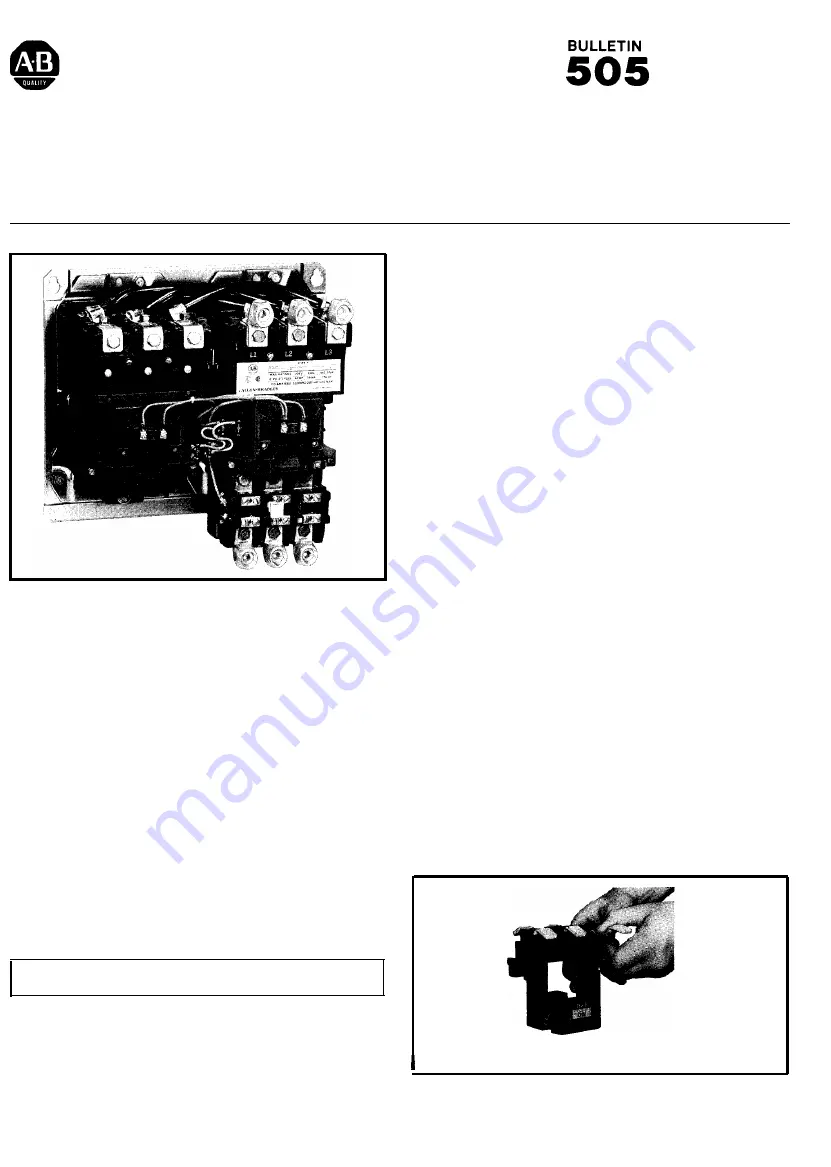
FULL VOLTAGE
REVERSING STARTERS - SIZE 4
OPERATION-
Bulletin 505 starters are most commonly used for
full voltage starting and reversing of polyphase squirrel cage
motors.
Bulletin 505 starters consist essentially of a “forward” and a
“reverse” contactor mounted to a common base. These
contactors are electrically and mechanically interlocked to
guard against both contactors closing at the same time.
Starters are equipped with Bulletin 592 block type manual
reset overload relays.
OPERATING ENVIRONMENT
- Starters should always be
maintained in a clean and dry condition for dependable
operation. Choice of the proper NEMA enclosure type for the
application is very important.
PREVENTIVE MAINTENANCE
- For recommended preventive
maintenance instructions refer to Publication GI-5.0 or the
Handy Catalog.
REPAIRS
- Contactors can be disassembled as depicted in the
“exploded” illustration on Page
procedures and techniques are suggested to aid in the
sequential disassembly and reassembly of a contactor.
WARNING
- Before part replacements are attempted the
POWER SOURCE MUST BE DISCONNECTED.
NOTE
- If parts are removed from both contactors, keep them
separateand replacethem in theiroriginal positions, if reused, to
avoid mismatched wear patterns.
DISASSEMBLY [Partial]
- The following instructions apply to
both the left hand and right hand contactors.
1. Remove all control wires from theoperating coil (Item 7) and
tie point terminal (Item 5). Tag removed wires.
2. Loosen two captive screws and lift off thecontact block cover
(Item 1).
3. Loosen four captive screws from the coil cover (Item 4). The
tie point terminal is now free to be removed, if it is to be
replaced.
4. With the coil cover screws loosened the auxiliary contact
block(s) (Item 6) can be removed and the coil cover lifted off.
5. Lift out the movable contact support and armature assembly
(Item 2), the yoke (Item 8) and theoperatingcoil (Item 7) as a
unit. The yoke and the operating coil can now be lifted up and
out of the movable contact support assembly.
REPLACING CONTACTS-With
steps 1-5 under DISASSEMBLY
completed inspect the contact surfaces for evidence of wear.
When severe contact wear is evidenced it is recommended that
all contacts be replaced. Replacing all contacts will guard
against uneven and unequal contact closings. Order the
required number of single pole contact sets from the part listings
Movable Contacts
- The following instructions describe the
replacement of movable contacts.
1. Remove the movable contact (Item 9) by depressing the
contact spring (Item 10) and pushing the contactouttoeither
side. The contact spring will fall free or can be lifted out.
2. Hold the replacement spring and contact in one hand as
shown in Figure 1.
3. Butt the contact spring against the side of the “seating
projection” on the movable contact support assembly. Slip
the movable contact through the opening on the movable
contact support assembly. Rock the spring into position over
the seating projection on the movable contact support and
the movable contact.
4. Check to determine that the spring is holding the contact
centered
Figure 1
Publication 505-6.3--November, 1981


