Aliencopter Quad's Flyman, User Manual
Introducing the Aliencopter Quad's Flyman - the ultimate aerial companion for enthusiasts! Take your drone experience to new heights with this cutting-edge quadcopter. To ensure you make the most of your Flyman, don't forget to download the comprehensive User Manual from our website. It's free and available for instant download at manualshive.com.
Share
Download


Reviews:
No comments
Related manuals for Quad's Flyman

250
Brand: Tarot Pages: 7

TETRAS 280
Brand: MSHELI Pages: 37

GT-3950
Brand: nimble Pages: 7

450 ARF QC09
Brand: Reely Pages: 168

zoopa q cruiser 420
Brand: ACME Pages: 42

MARK5
Brand: GEPRC Pages: 19
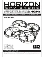
Horizon Spy Drone ZX-34895
Brand: World Tech Toys Pages: 8

Onset
Brand: Precision Drone Pages: 17

Pacesetter 2015
Brand: Precision Drone Pages: 60


