


1
ALI-NVR3304-08-16P_SQ
170707
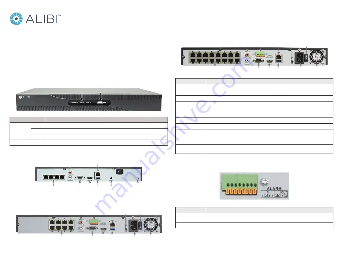
ALI-NVR3316P
Backpanel
Internal Ethernet switch
ports with PoE (16)
LAN
Fan
outlet
Video Out
(VGA, HDMI)
Audio
IN/OUT
Alarm
IN/OUT
USB
Power cord
connector
Power
switch
Ground
terminal
Item
Description
VIDEO OUT (VGA, HDMI)
1 channel (HDMI/VGA). See “Specifications” on page 4 for supported output resolutions.
Audio IN / OUT
RCA connectors for audio line input and line output
Alarm IN / OUT
Terminations are provided for 4 alarm inputs (N.O. or N.C.) and 1 alarm output. See below. (ALI-NVR3308P and ALI-NVR3316P only)
Power connector
ALI-NVR3304P: Connect the 48 Vdc power adapter provided with the recorder to this port, and to a standard 100 ~ 240 Vac power
source using the power cord provided.
ALI-NVR3308P and ALI-NVR3316P: Connect the power cord provided with the recorder to this port and to a standard 100 ~ 240 Vac
power source.
ON / OFF Switch
Switch for powering the recorder on or off.
GROUND
Terminal for ground. Connect to earth ground before powering on the NVR.
LAN
10/100BASE-T (ALI-NVR3304P) or 10/100/1000BASE-T (ALI-NVR3308P and ALI-NVR3316) Ethernet network interface
USB interface
Universal Serial Bus (USB) port for additional devices such as USB mouse and USB Hard Disk Drive (HDD). USB 3.0 port in ALI-NVR3308P
and ALI-NVR3316P only.
Internal Ethernet switch ports
4 (ALI-NVR3304P) or 8 (ALI-NVR3308P) or 16 (ALI-NVR3316P) 10/100 Mbps ports for IP cameras. These ports provide Power over
Ethernet (PoE).
Alarm IN / OUT Terminals
(ALI-NVR3308P and
ALI-NVR3316P
only)
Item
Description
ALARM IN (1 through 4 and
G, G (ground))
Alarm inputs 1 - 4. Alarm input is tied to ground at G or G terminals through the alarm sensor (N.O. or N.C.).
ALARM OUT (1 and G)
Alarm outputs 1 with ground termination.
Mouse control
A standard 3-button (left / right / scroll-wheel) USB mouse can also be used with this NVR. To use a USB mouse:
This quick setup guide provides instructions to initially setup and use the ALI-NVR3304P, ALI-NVR3308P and ALI-NVR3316P network
video recorders (NVRs). For information about using your NVR and its extensive capabilities, refer to the
Alibi Embedded Network Video
Recorder Firmware V3.4.x User Manual
provided at
www.alibisecurity.com/resources
.
For more information
, refer to these documents - available from your equipment vendor:
•
ALIBI™ Tools Utility Installation and User Manual
•
ALIBI™ Witness Smartphone App for Android - Quick Start Guide
Controls and Indicators
Front panel
Status indicators USB port
Item
Function / Description
Status Indicators
POWER
Indicator is green when the unit is powered on. When the unit is off, the LED is red if power is available.
HDD
HDD indicator blinks red when data is being read from or written to an HDD.
TX/RX
Blinks green when the network connection is functioning normally.
USB Interfaces
Universal Serial Bus (USB) 2.0 port for additional USB devices such as a mouse or Hard Disk Drive (HDD).
ALI-NVR3304P
Backpanel
Audio IN/OUT
Internal Ethernet switch
ports with PoE (4)
LAN
Power Adapter
connector
Power switch
Video Out
(VGA, HDMI)
Ground
terminal
USB
ALI-NVR3308P
Backpanel
Internal Ethernet switch
ports with PoE (8)
LAN
Fan
outlet
Video Out
(VGA, HDMI)
Audio
IN/OUT
Alarm
IN/OUT
USB
Power cord
connector
Power
switch
Ground
terminal
ALI-NVR3304P, ALI-NVR3308P, ALI-NVR3316P Embedded Network Video Recorders Quick Setup Guide


