


Copyright © 2015 Alarm.com
|
www.alarm.com
|
v1_2
1
Concord 4 LTE Module
|
Installation Guide
|
ADC-87-008700-112
Concord 4 Dual-Path LTE Module
INSTALLATION GUIDE
Introduction
The Dual-Path LTE Module for Concord 4 enables wireless reporting of all
alarms and other system events from the Interlogix Concord 4 control
panel using the LTE wireless cellular network and optional Ethernet
broadband network. The wireless alarm signaling and routing service is
operated by Alarm.com, and the Concord 4 LTE module also features
integrated support for Alarm.com’s emPower
TM
solution with built-in Z-
Wave capabilities.
The module interfaces with the Concord panel data bus and is powered
by the panel battery or an auxiliary 12 VDC power supply. Status LEDs
on the LTE module indicate bus and cellular network communications.
Contact Information
For additional information and support on Alarm.com products and
services, please visit
or contact Alarm.com
Technical Support at 1-866-834-0470.
Copyright © 2015 Alarm.com. All rights reserved
Compatibility
The module can be used on Concord 4.0 and higher to enable
Alarm.com’s interactive suite of services. This module is not compatible
with Concord 3.x or below panels.
Account Creation
Before installing the Alarm.com LTE Module in a Concord system, a new
customer account needs to be created with Alarm.com. We recommend
creating the account at least 24 hours in advance of installation to
ensure that the radio is activated prior to installation.
To activate an account, go to www.alarm.com/dealer and login. Under
the “Customers” heading at the top left of the page click on “Create New
Customer”. You will need the following customer information to create
the account:
•
Customer Name
•
Customer Address
•
Customer Phone Number
•
Customer E-mail
•
Preferred login name for the customer
•
Alarm.com Module Serial Number
At the end of the account creation process you will be able to print a
Welcome Letter for the customer that has their login information and
temporary password for the Alarm.com website.
Installation Overview & Guidelines
Before beginning the module installation, familiarize yourself with the
following installation guidelines and the location of the module and
troubleshooting LEDs and their function as shown in Figure 1 and Table
2, as they are referenced throughout this guide. Using these tips will
help guarantee a successful module installation.
1)
Create the customer account on the Alarm.com Dealer Site at least 24
hours before installation. See
Account Creation
above.
2)
Turn off the “Access Code Lock” feature on the panel. This feature
MUST be off for the system to communicate with Alarm.com.
3)
Installation consists of finding a mounting location for optimum
wireless signal strength, mounting the module, wiring the module, and
installing a case tamper (if necessary). Use the LTE Status LEDs on the
module to check the signal strength before you permanently mount the
module to avoid signaling issues after the installation is complete.
4)
Power the module off of the battery, not off of the panel (see
Wiring
on page 2).
5)
Perform a manual phone test (Comm Test) to initiate communication
(see
Power up
on page 3.)
6)
Observe panel power limitations as stipulated below:
•
The module draws a maximum of 65 mA (continuous) in PowerSave
Mode and 100 mA (continuous) in Idle Mode and Connected Mode
from the panel. The module can draw up to 1600 mA
(instantaneous peaks) from the panel.
•
Do not exceed the panel total output power when using panel
power for bus devices and hardwired sensors (refer to panel
documentation).
•
Use four-conductor, 22 or 18 gauge stranded wire to connect the
module to the panel. Table 1 shows the maximum wire length for
each gauge.
Table 1: Maximum wire length
Gauge
Maximum Wire Length
22 gauge
40 ft. (12.2 m)
18 gauge
90ft. (27.4 m)
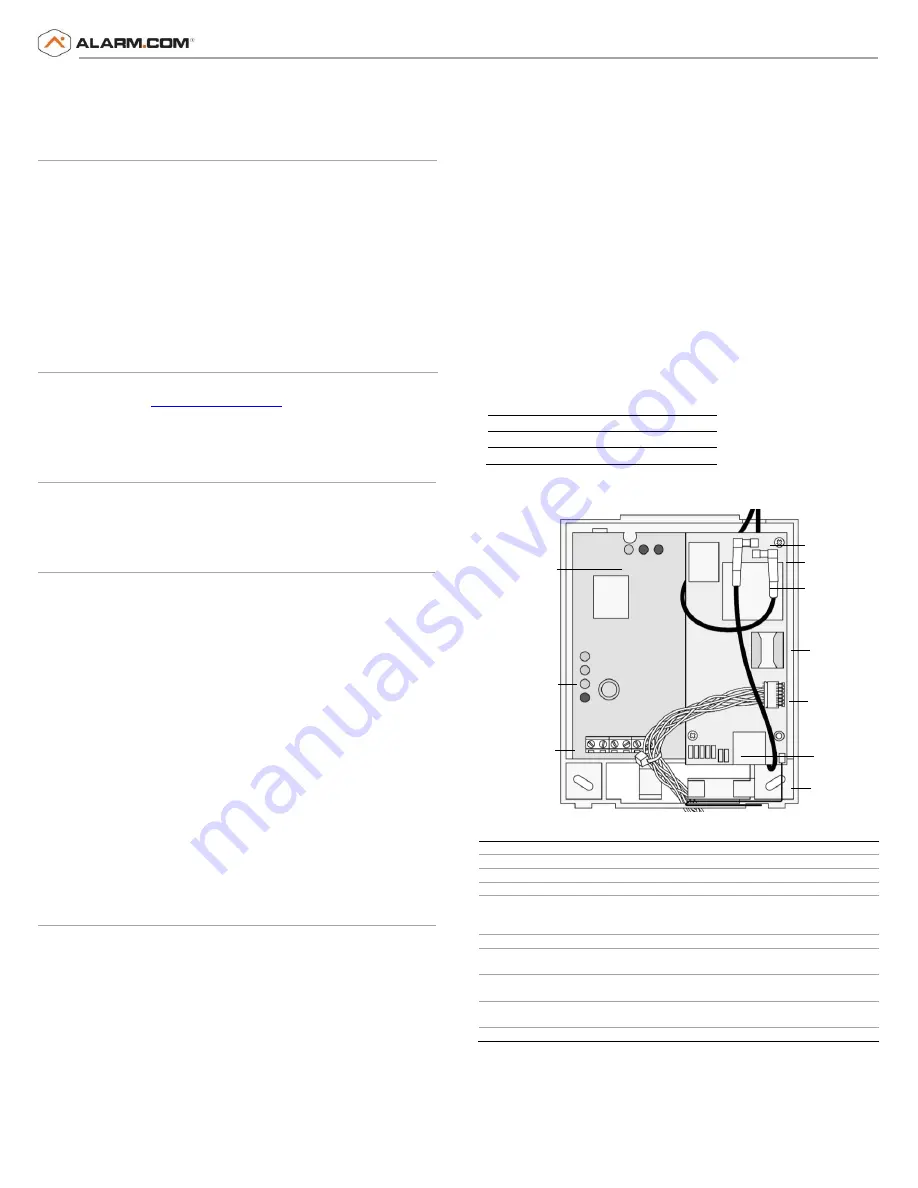
Figure 1: Main module components
Table 2: Component Descriptions
Component
Function
PWR LED
Indicates module power status.
BUS LED
Indicates data bus activity between the panel and module.
AUTO LED
Indicates module/data transceiver communication.
Gateway Status
LEDs
Indicates the current signal and status of the wireless gateway
module. Only the lower three LEDs are used (See
Gateway Status
LEDs
on page 4 for more information.)
Wiring terminals
Provides wiring connection to the panel.
Antenna
Connectors
Snap-in MMCX antenna connectors. The larger antenna connects
to connector 1, the smaller antenna connects to connector 2.
Module status
LEDs
Indicates communication with the LTE network, report errors, and
signal strength.
Serial number
A 15-digit number. Only the last 10 digits (after the dash “-“) are
used for account activation.
SIM Card
Required for LTE communication.
Figure 2 on page 2 shows the LTE status LEDs and Table 3 on page 2
describes the LED functions. See
Module Status LEDs
on page 4 for
more information.
PWR LED
BUS LED
AUTO LED
Gateway
Status LEDs
Wiring
Terminals
Antenna Connector 1
Antenna Connector 2
Serial Number
Ethernet Plug In
Module Status LEDs
Copper Z-Wave
Antenna
SIM Card


