Air Techniques VistaCam Omni IC4, Manual
The Air Techniques VistaCam Omni IC4 is a cutting-edge dental camera that captures high-quality images for professional use. Enhance your dental practice with this state-of-the-art device. For detailed instructions, simply download the free manual from our website and explore the full potential of this exceptional tool.
Share
Download


Reviews:
No comments
Related manuals for VistaCam Omni IC4

SECURICAM Network DCS-900
Brand: D-Link Pages: 20

SECURICAM Network DCS-2120
Brand: D-Link Pages: 25

DCS-6620G - Network Camera
Brand: D-Link Pages: 16

DCS-930L
Brand: D-Link Pages: 7

DCS-5220
Brand: D-Link Pages: 24

WIRELESS G DCS-950G
Brand: D-Link Pages: 2
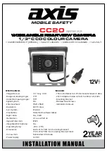
axis CC20 Series
Brand: Audioxtra Pages: 3

AH21K9M
Brand: A-MTK Pages: 6
SD7021
Brand: HANNspree Pages: 13

SP-560 UZ - Compact
Brand: Olympus Pages: 3

SP-560 UZ - Compact
Brand: Olympus Pages: 96

SP-510UZ
Brand: Olympus Pages: 96

SP-320
Brand: Olympus Pages: 84

SP 570 - UZ Digital Camera
Brand: Olympus Pages: 4

SP-320
Brand: Olympus Pages: 191
SP 700 - 6 Megapixel Digital Camera
Brand: Olympus Pages: 187
SP 320 - Digital Camera - 7.1 Megapixel
Brand: Olympus Pages: 191

SP 100EE
Brand: Olympus Pages: 109


