AIC RSC-1R, User Manual
The AIC RSC-1R is a versatile and reliable product, perfect for a variety of applications. For detailed instructions on how to maximize its potential, download the free User Manual from our website. Get the most out of your device with step-by-step guidance and troubleshooting tips.
Share
Download


Reviews:
No comments
Related manuals for RSC-1R

XenaBay C4-12
Brand: Xena Networks Pages: 6

FCM-CHS2 Series
Brand: AAxeon Pages: 16

HPS-3
Brand: ViaLite Pages: 34

Prosody X
Brand: aculab Pages: 22

GZ-FAEA41-CJB
Brand: Gigabyte Pages: 12

ChromaFlex
Brand: ATX Pages: 90

VXI-1501
Brand: National Instruments Pages: 6

Draco vario 474 Series
Brand: Ihse Pages: 77

M9010A PXIe
Brand: Keysight Technologies Pages: 18

AXIe Series
Brand: Keysight Technologies Pages: 22

M9502A AXIe
Brand: Keysight Technologies Pages: 28

M9506A
Brand: Keysight Technologies Pages: 41

M9506A-BC1
Brand: Keysight Technologies Pages: 96
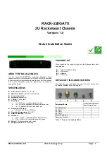
RACK-220GATX
Brand: IEI Technology Pages: 8


