background image

Page 1 of 17 

User Manual


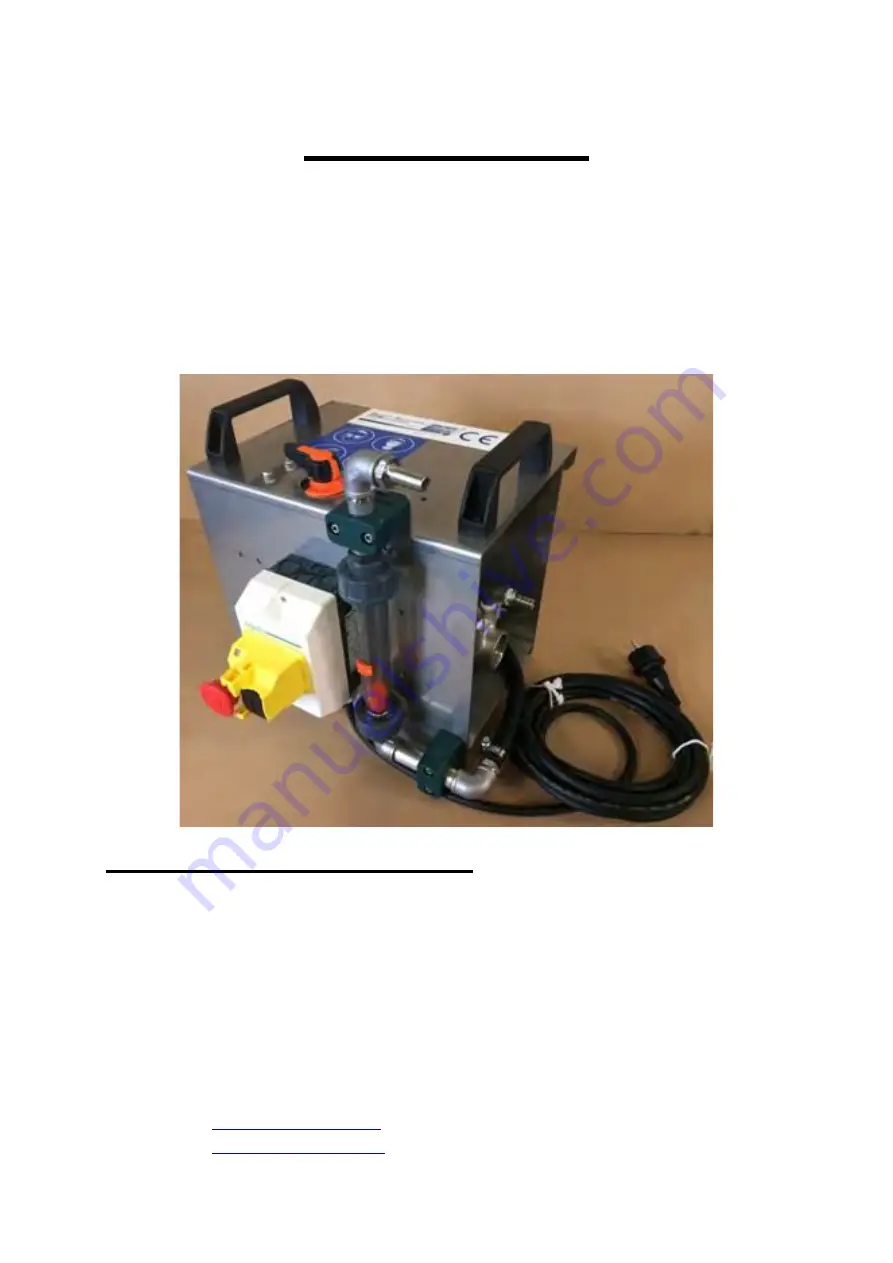
Standard 400/600/950 E


(Article No. 150-00) 

(Article No. 150-00-06) 
(Article No. 150-00-08) 


Version as of 06/2020


Consulting, Production & Sales:


Ahlmer Maschinen & Gerätebau 
GmbH & Co. KG


Schildarpstraße 20 

D - 48712 Gescher 

Germany 


Tel.:  +49 (0) 25 42 917917-0 

Fax:  +49 (0) 25 42 917917-29 


Website: 

www.amg-gmbh.com


Email: 

[email protected]


Summary of Contents for 150-00

Page 1: ...rticle No 150 00 06 Article No 150 00 08 Version as of 06 2020 Consulting Production Sales Ahlmer Maschinen Gerätebau GmbH Co KG Schildarpstraße 20 D 48712 Gescher Germany Tel 49 0 25 42 917917 0 Fax 49 0 25 42 917917 29 Website www amg gmbh com Email info amg gmbh com ...

Page 2: ...Page 2 of 17 Important Each time before starting the pump the device must be completely filled with water Important The pump can only be run dry for short periods Important ...

Page 3: ...e time process required exclusively for first commissioning 3 Fully open the control valve 6 by turning it counter clockwise 4 Use the black button on the switch housing to switch on the pump 5 Use the red emergency stop switch to switch off the pump To restart the pump turn the red emergency stop switch clockwise Important The pump must not run dry for more than 1 minute After a short time the fl...

Page 4: ...e must be rinsed with water from time to time The same applies when the device has not been used for several days At the beginning of the frost season the device must be topped up with antifreeze Wear acid resistant gloves safety glasses and a respiratory mask during all work Your safety is of paramount importance When working with preservatives always have a bucket of clear water within reach In ...

Page 5: ...ed rooms and or poured into reservoirs and silos or onto threshing floors the acid smell may cause a nuisance to the personnel working there Good ventilation of the storage rooms should therefore be ensured during this time If possible consider the wind direction when selecting a set up location for the dosing device The unpleasant smell will disappear a few minutes after the dosing process and or...

Page 6: ...ce to the acid tank Activation of the equipment combination and monitoring during operation 2 Integration of the dosing device into the work process The device can be integrated into all common work processes in the area of feed grain storage conveyor screw or trough conveyor The dosing device uses at least 2 dosing nozzles or 3 nozzles in case of grain maize to add the preservative at the respect...

Page 7: ...veyor tube The nozzle holders must be attached to the lower end of the screw downstream of the grain inlet The drill hole must have a diameter of approx 16 mm The nozzle holders should be placed at a distance of 1 5 times the spiral coil of the screw approx 20 cm ...

Page 8: ... the suction pipe and one bucket each for the return pipe and the nozzle hoses Caution At the end of the season after completion of this cleaning process the line system must additionally be rinsed with antifreeze Caution Frost risk Shortly before switching off the device the suction pipe should be pulled up so that most of the liquid will be sprayed out After that switch off the device Important ...

Page 9: ...tsoever for any damages and malfunctions resulting from improper handling e g dropping of the device poor maintenance damages caused during transport and unpacking damages resulting from poor packaging during further shipment or malfunctions due to natural wear and tear Any claims under this guarantee must first be asserted against a responsible seller For the purpose of fulfilling the guarantee o...

Page 10: ...perating the device Exceptions to this requirement are trainees from the age of 16 who must however be supervised whilst working with the device Caution Pay attention to playing children All pressurised components such as hoses and fittings are to be checked for tightness from time to time Be aware that parts of the device might get damaged by leaking acid Acid may cause damages to coatings and or...

Page 11: ...e that the device is safe for operation Nozzles are subject to natural wear and tear which is why they must be regularly checked and replaced if required Increased flow rates and or irregular spray patterns e g due to wear and tear damage or soiling may result in deficiencies in the process or where chemical means are used damages Depending on the setting two substance nozzles may generate an aero...

Page 12: ...50 03 150 06 1 Spare Parts List Article no 150 01 Portable housing Article no 150 02 Mushroom pushbutton Article no 150 03 DFM 185 flow indicator complete unit Article no 150 06 1 Control valve Article no 150 02 mushroom pushbutton ...

Page 13: ...150 11 Motor pump 150 07 150 230V 400 150 09 150 10 150 11 Article no 150 07 Pump base Article no 150 230V 400 230 Volt motor Article no 150 09 Hose connection pressure side Article no 150 10 Pump Article no 150 11 Hose connection suction side ...

Page 14: ...ubes Article no 150 14 Double nipple Article no 150 42 3 8 hose connector Article no 150 15 Drip guard Article no 150 43 T piece Article no 150 16 Nozzle retaining nut Article no 150 44 Elbow fitting Art no 19 015 Nozzle insert 0 15 mm diameter colour green Art no 19 020 Nozzle insert 0 20 mm diameter colour yellow Art no 19 030 Nozzle insert 0 30 mm diameter colour blue Art no 19 040 Nozzle inser...

Page 15: ...27 150 25 150 21 1 Article 150 06 1 regulating unit Article no 150 19 hose connector Article no 150 21 pipe nipple 100 mm Article no 150 21 1 pipe nipple 60 mm Article no 150 22 T piece Article no 150 25 arc 90 IG IG Article no 150 27 arc 90 IG AG Article no 150 32 Proportional ball valve ...

Page 16: ...low indicator complete set Article no 150 24 Upper hose connection including union nut Article no 150 26 DFM 185 measuring cylinder Article no 150 28 Lower pressure connection including union nut Article no 150 29 O ring for DFM 185 Article no 150 30 Support ring Article no 150 31 Floater ...

Page 17: ...cles 100 23 100 24 100 25 100 26 Article no 100 23 Filter housing Article no 100 24 Filter insert Article no 100 25 O ring suction filter Article no 100 26 Filter cup Article no 150 33 Suction line connection Article no 150 34 Return line connection Article no 150 35 Return line Article no 150 36 Suction line Article no 150 37 Foot filter Article no 150 38 Cover ...

Reviews: