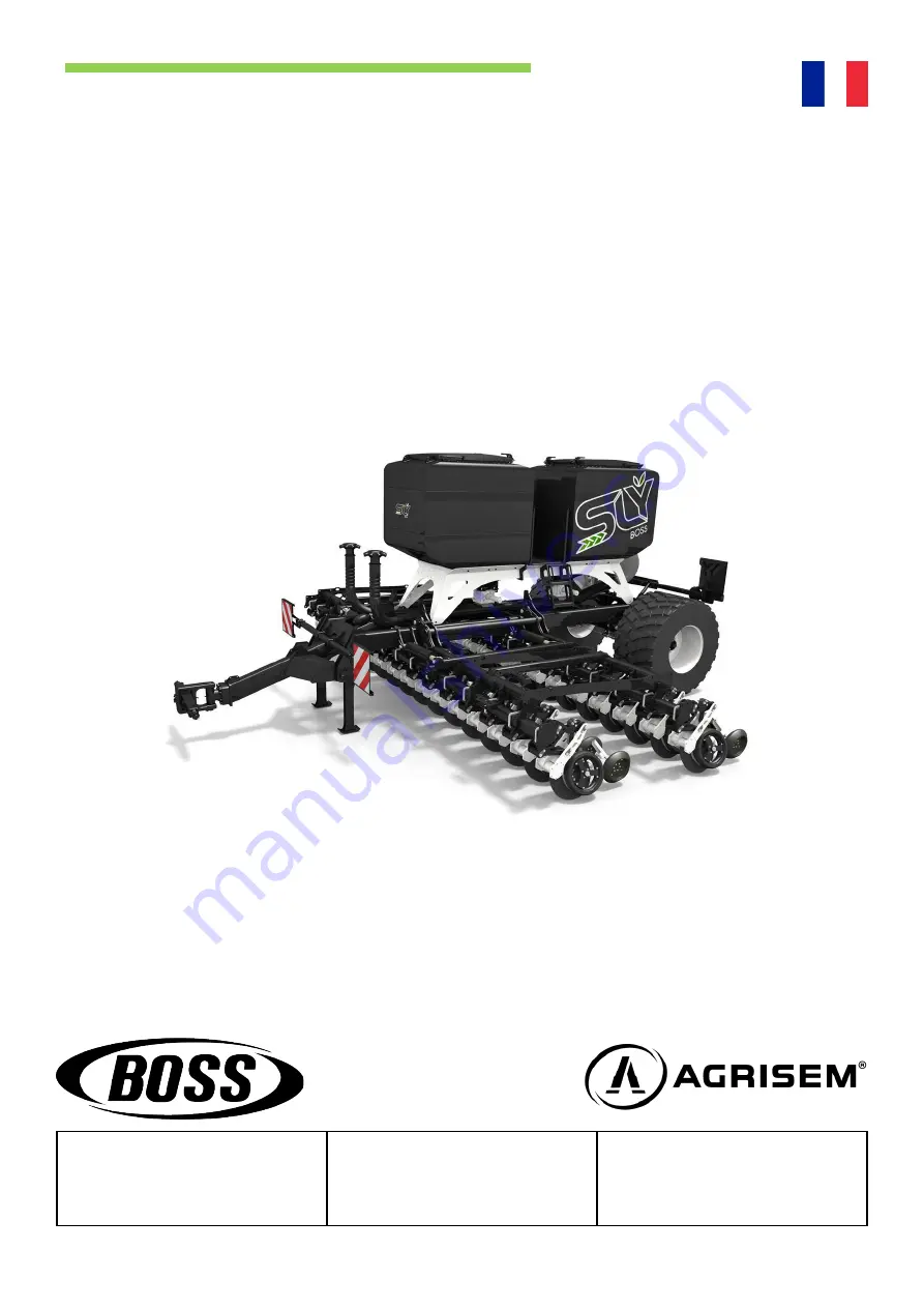
background image

USER MANUAL  

BOSS SEED DRILL


Telephone : +33 (0) 2 51 14 14 40

Mail : [email protected] 

Manual: NOTT-FR-800-A

AGRISEM

535 Rue Pierre Levasseur

CS 60263

44158 ANCENIS - FRANCE

Summary of Contents for Big Boss

Page 1: ...USER MANUAL BOSS SEED DRILL Telephone 33 0 2 51 14 14 40 Mail agrisem agrisem com Manual NOTT FR 800 A AGRISEM 535 Rue Pierre Levasseur CS 60263 44158 ANCENIS FRANCE ...

Page 2: ... of stickers 12 2 16 2 Placement of stickers 13 2 16 3 Placement of stickers on Boss machines 13 2 16 3 Placement of stickers on Big Boss machines 13 3 Technical specifications 14 3 1 Technical data 14 3 1 1 mBoss 14 3 1 2 Boss 14 3 1 3 Big Boss 15 3 2 Nameplate 15 3 3 Dimensions 16 3 4 Ballast calculation 18 4 Usage 19 4 1 Coupling 19 4 2 Hydraulic connection 19 4 3 Electrical connection 19 5 Sta...

Page 3: ...and hub assembly 40 10 1 1 18 disc 40 10 2 Safety reminder 41 10 3 Cleaning 41 10 4 Immobilising the tractor unit and machine 41 10 5 Storage 41 10 6 Maintenance 42 10 6 1 Daily maintenance and care 42 10 6 2 Annual maintenance 42 10 6 3 Lubrication point plan 43 11 Problems and troubleshooting 43 12 Annexes 45 12 1 Tightening torques 45 12 2 Choosing the rotors 46 12 2 1 Rotor models 46 2 12 2 Ro...

Page 4: ...f proper use defects that can lead to a complete breakdown can be caused by for example Damage due to external influences Wear and tear of wearing parts Missing or damaged work equipment Incorrect driving speeds Incorrect setting of the equipment incorrect assembly coupling failure to follow the setting instructions Non compliance with the user manual Maintenance and servicing not carried out or n...

Page 5: ...affixed to the component that is to be replaced they must also be ordered and affixed to the replacement component 2 3 User manual Intended use also includes complying with the instructions in the user manual and the manufacturer s operating maintenance and servicing instructions The user manual is an integral part of the machine The machine should only be used in accordance with the user manual F...

Page 6: ...gloves when handling disinfectants or seeds treated with disinfectants observe the disinfectant manufacturers instructions Determine the personal protective equipment for the respective task Make sure effective protective equipment is available and in good condition Never wear rings or other jewellery 2 8 Road safety Observe the permitted transport widths and heights Take into account the vehicle ...

Page 7: ...ydraulic system Brakes where applicable Connecting devices Protection devices Lights If there is any doubt as to the safe condition of the machine e g if consumable parts are leaking if there is visible damage or if the machine s behaviour has changed unexpectedly stop the machine immediately and secure it If possible determine the damage with the help of this user manual and eliminate it Eliminat...

Page 8: ... accumulator There may be pressure accumulators in the hydraulic system Do not open the pressure accumulators or do any work on them welding drilling Even after emptying the tanks are still under gas pressure The hydraulic system must be depressurised before maintenance work is carried out Never get on or off the machine under overhead lines to avoid the risk of electric shock from voltage dischar...

Page 9: ...9 11 Use in the field Before start up and commissioning make sure that no one is near the machine children Ensure that there is sufficient visibility Ensure sufficient stability of the machine in case of longitudinal and transversal slopes on uneven ground Observe the permitted limit values for the tractor None of the prescribed and supplied protective devices may be removed Ensure that no one is ...

Page 10: ...d to poisoning and death Observe the product manufacturer s safety data sheet If necessary ask the dealer for the safety data sheet Determine the required personal protective equipment according to the manufacturer s instructions and ensure its availability 2 11 Environmental protection Consumables such as hydraulic oil lubricants etc can harm the environment and people s health Do not allow consu...

Page 11: ...of at least 50 cm from the machine parts After cleaning check all hydraulic lines for leaks and loose connections Inspect for wear from friction and abrasion Immediately remedy any defects found Tighten all loose screw connections during servicing and maintenance work Do not wash new machines with steam or high pressure cleaners The paint only hardens after about 3 months and could be damaged befo...

Page 12: ...ons before commissioning and observe them during operation 355054 ETIQ01 625 Crushing danger area Never work in an area where there is a risk of crushing while parts are still moving 355063 ETIQ01 643 Keep a safe distance from power lines Keep a safe distance from high voltage power lines 355049 ETIQ01 617 Locking device Apply the locking device before any work is carried out 305064 ETIQ01 641 Hyd...

Page 13: ...355048 355016 355049 355054 380135 355063 x 2 x 2 355062 380299 305035 x 2 002 x 2 2 16 2 Placement of stickers on the mBoss 2 16 3 Placement of stickers on the Boss 2 16 4 Placement of stickers on Big Boss machines The safety stickers with the supplement x 2 are located on both sides of the machine Stickers Stickers Stickers Stickers ...

Page 14: ...d km h 16 7 Max transport speed km h 25 Operating width m 3 4 4 5 6 7 Transport width m 2 99 Transport height m 3 23 3 29 3 97 4 45 Length m 7 18 7 80 triple hoppers Weight kg 4 850 5 310 6 240 6 650 7 200 Single hopper capacity l 1 200 or 2 000 Double hopper capacity l 2 400 or 4 000 Triple hopper capacity l 3 600 or 6 000 Open filled hopper dims m 0 77 x 0 91 Height of filled hopper m 2 63 1200L...

Page 15: ...Weight kg 16 900 17 500 18 100 19 500 Single hopper capacity l 1 200 or 2 000 Double hopper capacity l 2 400 or 4 000 Triple hopper capacity l 3 600 or 6 000 Open filled hopper dims m 0 77 x 0 91 Height of filled hopper m 2 63 1200L hopper or 3 12 2000L hopper Number of seeding ploughshares 32 40 44 48 36 46 48 54 40 50 56 60 48 60 Row spacing cm 16 7 18 75 20 25 20 25 Transport wheels dims 500 60...

Page 16: ...mBoss seed drill 4 m 16 3 3 Dimensions BOSS seed drill 4 5m BOSS seed drill 3m mBoss seed drill 3 m ...

Page 17: ...17 BOSS seed drill 6m BOSS seed drill 7m Big Boss seed drill 8 9 10 12m Dimensions see table 3 1 Technical data 3 1 3 Big Boss 12 500 2 990 4 450 ...

Page 18: ...RAR Load transfer from the coupled machine a Distance between the centre of gravity of the front implement or front ballast and the centre of the front axle b Tractor wheelbase c Distance between the centre of the rear axle and the centre of the rear lower coupling point All weight data in kg All measurement data in m Calculation of the minimum ballast at the front Calculation of the actual front ...

Page 19: ... hydraulic valve for folding and unfolding the machine s wings 1 double acting hydraulic valve to raise and lower the seeding units in the field 1 double hydraulic valve for the use of markers optional 1 single acting to power the hydraulic turbine 1 free return male in 3 4 to the tractor s hydraulic oil tank for turbine oil return When using a tractor with a variable flow pump and integrated regu...

Page 20: ...5 1 1 Boss 1 Remove the safety pins from the wings 2 Activate the corresponding hydraulic control valve until the wings are completely unfolded Before unfolding the wings make sure that the seeding units are in the upper position 5 1 2 Big Boss 1 Manually unlock the wings by removing the locking pins on the main base brackets ...

Page 21: ...ring the entire unfolding process 3 Lift button 2 to unfold the lift assist and the side gauge wheels 4 Lift button 4 to unfold the side gauges 5 Lightly actuate the frame cylinders on the tractor to remove the wings from the locking system 6 Lift button 3 to open the wings 7 Slowly move the tractor forward to help unfold the wings ...

Page 22: ...mmobilised and that the wings are folded out 1 Remove the pin and shaft from the step located on the left rear row 2 To open the hoppers activate the locking levers 5 2 2 Filling Before filling the hoppers we recommend closing the flaps at the bottom of the hoppers When closing the hoppers ensure that no grain or foreign matter is trapped between the cover seal and the hopper After each opening of...

Page 23: ...nd a dust mask The work performed on a big bag is only done when the bag is stabilised 5 2 3 Emptying hoppers 1 Move the seed drill to the transport position 2 Place a big bag or container under the machine 3 Open the emptying flap on the side of the hopper 4 If necessary set the metering unit to forced operation to completely empty the bottom of the hopper 5 3 Small seed hopper As an option the B...

Page 24: ...e metering unit according to the quantity and type of seed see table and instructions for fitting the metering unit 2 Turn on the seed drill control tablet and go to the calibration settings menu see Using the tablet 3 Fill the hopper 4 Open the flap to release the seed or fertiliser 5 Open the flap under the metering unit activate the valve to direct the flow to the side chosen for calibration 6 ...

Page 25: ...exagonal shaft using a hammer and a pin punch Then insert the rotors corresponding to the type of seed and the chosen dose Each rotor has a specific volume adapt the choice of rotors to the desired volume Examples of rotors from left to right Star 3cc 3 cm Star 67 5cc 67 5 cm Start 202cc 202 cm Be sure to add full rotors before replacing the circlip Make sure that the rotation sensor of the meteri...

Page 26: ...s 1 Lift button 1 to activate the anti lifting device via the valve that supplies the CETOP This function must remain activated during the entire unfolding process 2 Move the tractor forwards at least 2 m to align the gauge wheels so that they can be locked 3 Lift button 6 for 10 seconds to unlock the gauge wheels Leave these wheels locked during transportation 4 Activate the frame cylinders on th...

Page 27: ...27 9 Lift button 2 to fold the lift assist and the side gauge wheels 10 Lower button 1 to remove the anti lifting device 11 Manually lock the wings by placing the locking pins on the main base brackets ...

Page 28: ... pressure applied to each unit is essential to obtain a satisfactory seed quality i e seeding at the desired and constant depth a good quality closing of the furrow Each seeding unit is equipped with a hydraulic cylinder to adjust the depth control pressure After setting the working depth adjust the hydraulic pressure of the unit Note the use of high pressure may alter the seeding depth adjust the...

Page 29: ...his can damage the engine To switch on the turbine engage the corresponding hydraulic valve and set it to the continuous pumping position Then adjust the hydraulic flow of the valve to adjust the speed of the turbine The speed of the turbine must be adjusted depending on the seeds There is no settings table because the setting will depend on the type of product and the doses used The usual operati...

Page 30: ...set by 2 3mm It should be possible to turn the disc by hand once the skimmer position has been set IMPORTANT These settings are essential to prevent debris and straw from jamming between the disc and the skimmer 6 6 Side wheel setting The depth control wheels should be against the ploughshare discs and be easily turned by hand On the Boss unit the side wheel has two purposes Limit and maintain the...

Page 31: ...the disc to work in its current position until the accumulation of mud and debris starts to cause problems 6 8 Disc cleaning scraper As standard the Boss unit is equipped with a scraper inside the cleaning wheel to clean the disc soil debris mixture The openwork rim of the cleaning wheel allows soil and debris to be removed The scraper blade must be in full contact with the disc 1 The entire lengt...

Page 32: ...rmost row is calculated on the basis of half the working width plus half the row spacing BOSS seed drill 3m Configurations Length of markers 18R 16 7cm 1 58 m 16R 20cm 1 7 m 16R 18 75cm 1 59 m 12R 25cm 1 63 m BOSS seed drill 4m Configurations Length of markers 24R 16 7cm 2 08 m 22R 18 75cm 2 15 m 20R 20cm 2 10 m 16R 25cm 2 12 m BOSS seed drill 4 5m Configurations Length of markers 24R 18 75cm 2 34...

Page 33: ...of the machine and trigger full braking when cornering 3 Release the parking brake The cables must not be stretched and the wheels must be able to turn freely Hydraulic brake 1 Push pull socket 2 Loosening pump button 3 Automatic uncoupling brake valve 4 Spring pin emergency activation 5 Pressure accumulator 6 Cylinders Danger of traffic accidents due to brake failure When commissioning or after a...

Page 34: ...ack to the operating position and activate the release pump until the brake is released again Maintenance Check the brake lines and hoses for damage Check the brake linings for wear 7 2 Pneumatic brake Coupling Secure the towing vehicle with the parking brake before coupling 1 First connect the Brake coupling head yellow 2 Then connect the Backup coupling head red 3 Press the parking brake button ...

Page 35: ...nd the wheels must be able to turn freely Maintenance When coupling the machine check the functioning of the parking brake If necessary adjust the cable or the brake shoes 8 Hydraulics Accidental hydraulic movements can lead to serious accidents Block or lock the valves on the tractor Keep people out of the pivoting range of the machine Always connect all hydraulic hoses Due to related functions d...

Page 36: ...6 8 1 2 Folding turbine circuit Folding circuit and turbine drive 1 Push pull socket 2 Valve 3 Double balancing valve 4 Safety gear valve 5 Cylinder 6 Check valve 7 Gauge 8 Hydraulic motor turbine drive ...

Page 37: ...ion with pressure limiter 4 cetop 3 solenoid valve 5 cetop 3 solenoid valve 6 Valve 7 Check valve 8 Cetop 3 1 base hydraulic function with pressure limiter 9 cetop 3 solenoid valve 10 Double balancing valve 11 Safety gear valve 12 Cylinder 13 Check valve 14 Gauge 15 Hydraulic motor turbine drive 8 1 3 Circuit with CETOP ...

Page 38: ...8 8 1 4 Circuit elements Circuit of components 1 Push pull socket 2 Valve 3 Unit pressure regulation cartridge 4 Pressure limiter 5 Pressure switch 6 Check valve 7 Pressure accumulator 8 Gauge 9 Cylinder ...

Page 39: ...age Lift assist Ailes T CETOP P P T Turbine R Blocage Lift assist T P Éléments Éléments Éléments Jauge AR Jauge AR Jauge AV Jauge AV Blocage roue Blocage roue T P Blocage roue Blocage roue Repliage des ailes T P T P T Dépliage jauge Dépliage jauge T P P Éléments ...

Page 40: ...isc and hub assembly 10 1 1 18 disc A new Boss unit disc has a diameter of 18 approximately 457 mm This is equipped with a bevel that facilitates penetration into the soil and the cutting of plant debris straw and living cover thus greatly limiting the effect of straw trapping in the seed line which is harmful to seeding Discs should be replaced when they reach a diameter of 425mm 133mm between th...

Page 41: ...cover if possible When operating the machine take the environment into account Ensure that no one is in the manoeuvring area Park the machine on solid ground if you leave it parked for a long period of time it is advisable to leave the machine in the unfolded position or in the working position Immobilisation of unfolded implement 1 Follow the steps to unfold the machine but stop once all working ...

Page 42: ...ry Visually inspect all bolts and nuts retighten any bolts nuts that need tightening Lubricate the opener disc hub with 1 2 bursts maximum of a grease gun every 12 working hours excessive lubrication will cause the seals to be dislodged from their housing 10 6 2 Annual maintenance Lubricate the opener disc hub with 2 bursts maximum of a grease gun every 12 working hours excessive lubrication will ...

Page 43: ...roperly closed and pressed Incorrect height under beam when working Check the height under the frame beam Not enough pressure on the press wheels Increase the depth control pressure of the unit See Chapter 6 Press wheel not aligned with the furrow Change the position of the press wheel See Chapter 6 The furrow is too deep The press wheel pressure is too high Reduce the depth control pres sure of t...

Page 44: ...ed placement is inconsistent The depth control pressure of the unit is too low Increase the depth control pressure to ensure a constant seeding depth See Chapter 6 The machine frame is not level Adjust the machine s level See Chapter 4 The height under the beam when working is incorrect Check the height under the beam when working and adjust if necessary See Chapter 4 The seeding ploughshare is cl...

Page 45: ...he tightening torques are for guidance only and are generally valid The specific instructions in the relevant sections of the user manual take precedence Screws and nuts should not be treated with any lubricants as they change the friction coefficient ...

Page 46: ...32 C Star 0cc black wide 0 6 SLY S109 831 D Star 0cc plastic 0 2 SLY S111 849 E Star 1cc 1 1 SLY S116 081 F Star 2cc 2 1 SLY S112 475 G Star 3cc 3 1 SLY S111 451 H Star 5cc 5 1 SLY S112 476 I Star 15cc narrow 15 1 SLY S112 478 J Star 15cc wide 15 2 SLY S112 473 K Star 25cc 25 2 SLY S112 469 L Star 67 5cc 67 5 2 SLY S109 833 M Star 202cc 202 6 SLY S109 834 ...

Page 47: ... width 337 5 L B L B L B L B L N 67 5 0 67 5 0 67 5 0 67 5 0 67 5 volume 2 2 2 2 2 2 2 2 2 width 337 B L B M B L B N 0 67 5 0 202 0 67 5 0 volume 2 2 2 6 2 2 2 width 270 B L B L B L B L B N 0 67 5 0 67 5 0 67 5 0 67 5 0 volume 2 2 2 2 2 2 2 2 2 width 270 B L L C L L B N 0 67 5 67 5 0 67 5 67 5 0 volume 2 2 2 6 2 2 2 width 202 5 B B L B L B L B B N 0 0 67 5 0 67 5 0 67 5 0 0 volume 2 2 2 2 2 2 2 2 ...

Page 48: ...0 25 0 volume 2 2 2 2 2 2 2 2 2 width 75 B J B J J J B J B N 0 15 0 15 15 15 0 15 0 volume 2 2 2 2 2 2 2 2 2 width 75 B K B B K B B K B N 0 25 0 0 25 0 0 25 0 volume 2 2 2 2 2 2 2 2 2 width 60 B J J B B B J J B N 0 15 15 0 0 0 15 15 0 volume 2 2 2 2 2 2 2 2 2 width 60 B J B J B J B J B N 0 15 0 15 0 15 0 15 0 volume 2 2 2 2 2 2 2 2 2 width 60 D D D I I D I I D D D N 0 0 0 15 15 0 15 15 0 0 0 volum...

Page 49: ...me 2 2 2 1 1 2 1 1 2 2 2 width 12 D D D G G D G G D D D N 0 0 0 3 3 0 3 3 0 0 0 volume 2 2 2 1 1 2 1 1 2 2 2 width 10 D D D A H D H A D D D N 0 0 0 0 5 0 5 0 0 0 0 volume 2 2 2 1 1 2 1 1 2 2 2 width 8 D D D F F D F F D D D N 0 0 0 2 2 0 2 2 0 0 0 volume 2 2 2 1 1 2 1 1 2 2 2 width 6 D D D A G D G A D D D N 0 0 0 0 3 0 3 0 0 0 0 volume 2 2 2 1 1 2 1 1 2 2 2 width 4 D D D A F D F A D D D N 0 0 0 0 2...

Page 50: ...142 49 113 41 95 C270 Barley 243 567 162 378 122 284 97 227 81 189 C400 Barley 360 840 240 560 180 420 144 336 120 280 C600 Barley 540 1260 360 840 270 630 216 504 180 420 Wheat Min Motor speed 30 rpm Max Motor speed 80 rpm Seed density 0 8 SW Specific weight Spline in CM3 Spline pictures Seeds 3 metres Speed km h 4 6 8 10 12 Dose per hectare in kg Ha Min Max Min Max Min Max Min Max Min Max C135 W...

Page 51: ...1 C270 Barley 182 425 122 284 91 213 73 170 61 142 C400 Barley 270 630 180 420 135 315 108 252 90 210 C600 Barley 405 945 270 630 203 473 162 378 135 315 Wheat Min Motor speed 30 rpm Max Motor speed 80 rpm Seed density 0 8 SW Specific weight Spline in CM3 Spline pictures Seeds 3 metres Speed km h 4 6 8 10 Dose per hectare in kg Ha Min Max Min Max Min Max Min Max C135 Wheat 122 284 81 189 61 142 49...

Page 52: ...4 5 3 1 8 4 1 6 3 Rotor volume 135 5 cm3 Rotor volume 271 cm3 Rotor volume 406 cm3 Kg ha Speed of travel Min Avg Max Min Avg Max Min Avg Max 50 8 1 18 3 28 5 16 3 36 6 56 9 24 4 54 8 85 3 60 6 8 15 2 23 7 13 6 30 5 47 4 20 3 45 7 71 1 70 5 8 13 1 20 3 11 6 26 1 40 7 17 4 39 2 60 9 80 5 1 11 4 17 8 10 2 22 9 35 6 15 2 34 3 53 3 90 4 5 10 2 15 8 9 0 20 3 31 6 13 5 30 5 47 4 100 4 1 9 1 14 2 8 1 18 3...

Page 53: ...8 8 0 18 0 28 0 6 3 3 7 5 11 7 4 0 9 0 14 0 6 7 15 0 23 3 7 2 9 6 4 10 0 3 4 7 7 12 0 5 7 12 9 20 0 8 2 5 5 6 8 8 3 0 6 8 10 5 5 0 11 3 17 5 9 2 2 5 0 7 8 2 7 6 0 9 3 4 4 10 0 15 6 10 2 0 4 5 7 0 2 4 5 4 8 4 4 0 9 0 14 0 15 1 3 3 0 4 7 1 6 3 6 5 6 2 7 6 0 9 3 20 1 0 2 3 3 5 1 2 2 7 4 2 2 0 4 5 7 0 25 0 8 1 8 2 8 1 0 2 2 3 4 1 6 3 6 5 6 Rotor volume 30 cm3 Rotor volume 50 cm3 Rotor volume 60 cm3 Kg...

Page 54: ... 40 6 80 3 4 7 6 11 9 6 8 15 2 23 7 10 2 22 8 35 5 90 3 0 6 8 10 5 6 0 13 6 21 1 9 0 20 3 31 6 100 2 7 6 1 9 5 5 4 12 2 19 0 8 1 18 3 28 4 120 2 3 5 1 7 9 4 5 10 2 15 8 6 8 15 2 23 7 140 1 9 4 4 6 8 3 9 8 7 13 6 5 8 13 1 20 3 160 1 7 3 8 5 9 3 4 7 6 11 9 5 1 11 4 17 8 180 1 5 3 4 5 3 3 0 6 8 10 5 4 5 10 2 15 8 200 1 4 3 0 4 7 2 7 6 1 9 5 4 1 9 1 14 2 220 1 2 2 8 4 3 2 5 5 5 8 6 3 7 8 3 12 9 240 1 ...

Page 55: ... 8 8 0 18 0 28 0 6 3 3 7 5 11 7 4 0 9 0 14 0 6 7 15 0 23 3 7 2 9 6 4 10 0 3 4 7 7 12 0 5 7 12 9 20 0 8 2 5 5 6 8 8 3 0 6 8 10 5 5 0 11 3 17 5 9 2 2 5 0 7 8 2 7 6 0 9 3 4 4 10 0 15 6 10 2 0 4 5 7 0 2 4 5 4 8 4 4 0 9 0 14 0 15 1 3 3 0 4 7 1 6 3 6 5 6 2 7 6 0 9 3 20 1 0 2 3 3 5 1 2 2 7 4 2 2 0 4 5 7 0 25 0 8 1 8 2 8 1 0 2 2 3 4 1 6 3 6 5 6 Rotor volume 30 cm3 Rotor volume 50 cm3 Rotor volume 60 cm3 K...

Page 56: ...7 3 3 1 7 0 10 9 280 1 0 2 2 3 4 1 9 4 4 6 8 2 9 6 5 10 2 300 0 9 2 0 3 2 1 8 4 1 6 3 2 7 6 1 9 5 320 0 8 1 9 3 0 1 7 3 8 5 9 2 5 5 7 8 9 Rotor volume 4 cm3 Rotor volume 6 cm3 Rotor volume 8 cm3 Kg ha Speed of travel Min Avg Max Min Avg Max Min Avg Max 1 5 3 12 0 18 7 8 0 18 0 28 0 10 7 24 0 37 3 2 2 7 6 0 9 3 4 0 9 0 14 0 5 3 12 0 18 7 3 1 8 4 0 6 2 2 7 6 0 9 3 3 6 8 0 12 4 4 1 3 3 0 4 7 2 0 4 5 ...

Page 57: ...me 406 cm3 Kg ha Speed of travel Min Avg Max Min Avg Max Min Avg Max 25 7 2 16 3 25 3 14 5 32 5 50 6 21 7 48 7 75 8 30 6 0 13 6 21 1 12 0 27 1 42 2 18 0 40 6 63 2 35 5 2 11 6 18 1 10 3 23 2 36 1 15 5 34 8 54 1 40 4 5 10 2 15 8 9 0 20 3 31 6 13 5 30 5 47 4 45 4 0 9 0 14 1 8 0 18 1 28 1 12 0 27 1 42 1 50 3 6 8 1 12 6 7 2 16 3 25 3 10 8 24 4 37 9 60 3 0 6 8 10 5 6 0 13 6 21 1 9 0 20 3 31 6 70 2 6 5 8...

Page 58: ... 5 6 8 8 3 0 6 8 10 5 5 0 11 3 17 5 7 2 1 4 8 7 5 2 6 5 8 9 0 4 3 9 6 15 0 8 1 9 4 2 6 6 2 3 5 1 7 9 3 8 8 4 13 1 9 1 7 3 8 5 8 2 0 4 5 7 0 3 3 7 5 11 7 10 1 5 3 4 5 3 1 8 4 1 6 3 3 0 6 8 10 5 15 1 0 2 3 3 5 1 2 2 7 4 2 2 0 4 5 7 0 20 0 8 1 7 2 6 0 9 2 0 3 2 1 5 3 4 5 3 Rotor volume 30 cm3 Rotor volume 50 cm3 Rotor volume 60 cm3 Kg ha Speed of travel Min Avg Max Min Avg Max Min Avg Max 6 7 5 16 9 ...

Page 59: ...20 0 9 2 1 3 2 1 8 4 2 6 5 2 8 6 2 9 7 240 0 8 1 9 3 0 1 7 3 8 5 9 2 5 5 7 8 9 260 0 8 1 8 2 7 1 6 3 5 5 5 2 3 5 3 8 2 280 1 0 1 6 2 5 1 5 3 3 5 1 2 2 4 9 7 6 300 0 9 1 5 2 4 1 4 3 0 4 7 2 0 4 6 7 1 Rotor volume 4 cm3 Rotor volume 6 cm3 Rotor volume 8 cm3 Kg ha Speed of travel Min Avg Max Min Avg Max Min Avg Max 1 4 0 9 0 14 0 6 0 13 5 21 0 8 0 18 0 28 0 2 2 0 4 5 7 0 3 0 6 8 10 5 4 0 9 0 14 0 3 1...

Page 60: ...e 406 cm3 Kg ha Speed of travel Min Avg Max Min Avg Max Min Avg Max 15 9 0 20 3 31 6 18 1 40 7 84 3 27 1 60 9 94 7 20 6 8 15 2 23 7 13 6 30 5 63 2 20 3 45 7 71 1 25 5 4 12 2 19 0 10 8 24 4 50 6 16 2 36 5 56 8 30 4 5 10 2 15 8 9 0 20 3 42 2 13 5 30 5 47 4 35 3 9 8 7 13 6 7 7 17 4 36 1 11 6 26 1 40 6 40 3 4 7 6 11 9 6 8 15 2 31 6 10 2 22 8 35 5 45 3 0 6 8 10 5 6 0 13 6 28 1 9 0 20 3 31 6 50 2 7 6 1 ...

Page 61: ...61 12 4 SeedXconnect manual 12 4 1 Description 12 4 1 1 Microsoft Surface Pro 7 12 4 1 2 Microsoft Surface Go ...

Page 62: ... 10 Sown quantities or quantities in the metering unit 11 Control of instantaneous dose while working 12 Dose per hectare 13 Manual modification of the dose per hectare 14 Locking of individual metering units or of all metering units 15 Switching on all metering units manually and choosing which ones to switch on 16 Timer delay adjustable in the settings Note when one of these 3 options is active ...

Page 63: ...unit is counting down 3 The number in the centre that appears in red indicates that the sensor at the top of the metering unit is uncovered 4 The square is displayed in red when the metering unit is empty 12 4 2 3 Managing tramlining tramlining on or off and the number of runs be made the seed line when tramlining left tramline deactivation and reactivation of tramlining manual modification of the...

Page 64: ...4 Managing plots 1 Press field 1 Total number of hectares or 2 Number of hectares for a plot 2 Press icon 3 to display the work history 3 If desired export the history data in the desired format Word Excel or XML ...

Page 65: ...65 12 4 2 5 Stopping the console 1 From the work page press button 1 Settings 2 Press button 2 Start Stop 3 Press button 3 Stop the console to leave the application ...

Page 66: ...work page press button 1 Settings 2 Press button 2 Machine to configure the machine 3 Set the various parameters 3 Name of the metering unit 4 Metering unit status on or off 5 Working width 6 Timer delay 7 Total area to be treated 8 Cruising speed target speed for work ...

Page 67: ...Metering unit X button 3 4 Set the various parameters 4 Metering unit name 5 Flow test start button 6 Calibration list access to old measurements 7 Number of grams per revolution of the metering unit motor 8 Minimum and maximum permitted working speed 9 Information on the installed spline 10 Number of revolutions per minute of the metering unit this speed must be between 30 and 70 rpm 11 Desired q...

Page 68: ...tion press button 5 again Test end and confirm the message that appears 7 Press field 13 Output to enter the weight value of the quantity actually output from the metering unit 8 Press button 14 Validate to confirm the value entered and confirm the message that appears 9 If you wish save this new calibration to the list ...

Page 69: ...ng to configure the tramlining 3 Press button 6 Sequence calculation to configure the tramlining The different information displayed 3 The different runs 4 Tramline diagram 5 Tramline or not and tramline type 6 Button for calculating the sequence 7 Starting direction indicated by the red dot left or right 8 Working width of the sprayer ...

Page 70: ...the work page press button 1 Settings 2 Press button 2 Tramlining to configure the tramlining 3 Use the arrow 3 to select the desired tramline type for each run 4 No tramline 5 1 tramline to the LEFT 6 2 tramlines in the CENTRE 7 1 tramline to the RIGHT ...

Page 71: ...button 1 Settings 2 Press button 2 Alarms to configure the tramlining 3 Press the button corresponding to an alarm to activate it it will appear in green or deactivate it it will appear in grey 4 Press button 3 Turbine rotation to enter the alarm threshold values ...

Page 72: ...72 12 5 A Touch 800 1200 manual 12 5 1 Description 12 5 1 1 Front A Touch 1200 A Touch 800 12 5 1 2 Rear ...

Page 73: ...73 12 5 1 3 Icons ...

Page 74: ...g width 1 Open the home screen 2 Press button 1 Settings to open the settings screen 3 Press button 2 twice Next page to open page 3 of the settings screen 4 Press Work position sensor 1 5 If your machine has the Cut Out function select Work position sensor 1 in the list ...

Page 75: ...oximately 5 m 12 5 2 2 Managing the product database 1 Open the home screen 2 Press button 1 Settings to open the settings screen 3 Press field 2 Product to display the product list 4 Select the product to be checked or configured from the database Choose a free field to add a new product 5 Press field 3 Instruction to change or configure the spreading instruction 6 Press button 4 Next pageto go t...

Page 76: ...tton 6 Product to open the Product assigned in the product database 8 Set the various parameters 9 Press button 7 Scroll down to go to the next settings pages Once all the settings have been adjusted as desired 10 Press button 8 Back to confirm your changes and exit the product database ...

Page 77: ...king widths of the seed drill and sprayer a Choose whether to start working at the left or right edge of the field b Divide the working width of the sprayer by the working width of the seed drill c Refer to the user manual of your pneumatic seed drill to select the tramline pattern according to the result of the division calculation even odd or decimal 4 Use the control wheel to navigate through t...

Page 78: ...m Division 21 3 7 runs of the seed drill for 1 run of the sprayer 1 In the table select the row 7 7 _ 4 _ 4 with the control wheel and then press the control wheel to confirm 2 Press button 3 Back to leave the settings screen 3 Press button 3 again Back to return to the main menu The tramline valves are activated on the 4th run ...

Page 79: ...n the side from which you start to cover the field 1 In the table select the row 8G 8 5 4 0 0 with the control wheel and then press the control wheel to confirm Note as in the example we start from the left of the field we choose the 8G configuration 2 Press button 3 Back to leave the settings screen 3 Press button 3 again Back to return to the main menu The left tramline valve is activated on the...

Page 80: ... run if there are several lifts and drops on the same run 12 5 2 5 Adjusting the dose In the operating display to temporarily change the delivered dose 1 Press button 1 Manual adjustment of dose 2 Press the buttons 2 Decrease the dose to decrease the corresponding dose in 10 increments 3 Press the buttons 3 Increase the dose to increase the corresponding dose in 10 increments 4 To cancel this temp...

Page 81: ...e seed drill is active 2 Press button 2 Area information to display the information screen The following information is displayed since the counters were last reset The area sown The volume applied The hourly output 3 Press button 3 Reset to reset the counters to zero 4 Press key 4 Total counters to display the total counters these counters cannot be reset ...

Page 82: ...lected assignment 8 Press button 8 Start assignment to start the selected assignment The assignment starts To suspend and resume the assignment press button 8 which alternates between Restart assignment and Suspend assignment Press button 9 Back several times to return to the main operating display To delete the assignment press button 10 Delete assignment ...

Page 83: ... 3 Press button 1 Speed settings 4 Select the speed source 2 Tractor 3 Radar by default 4 Simulation Note In simulation introduce the simulated speed to be used to test the machine in static mode 5 Press button 5 Calibration start 6 Cover the 100m distance marked in the field and stop at the end 7 Press button 6 Confirmation ...

Page 84: ...select the metering unit that you want to calibrate 5 In field 4 Mode selectManual mode 6 Press the Calibration button on the machine 7 Weigh the actual amount extracted during the calibration process 8 In field 5 Valued weighed enter the actual value weighed Note if the calculatedDeviation is greater than 5 repeat the calibration 9 Check that theMin andMaxSpeeds are consistent 10 Press button 6 C...

Page 85: ...owing buttons to update the page to go to the next page to go back to the previous page 3 Press button 3 Diagnostics to open the diagnostics page The following screens and functions are displayed in turn Function 0 1 2 3 MA15 and MA41 motor 1 MA28 and MA35 motor 2 1S15 and 1S15 motor 3 1S35 and 1S28 motor 4 To test the motor Set the LS output value to 50 The motor should be running at 50 of its ca...

Page 86: ...on 31 93 94 95 96 97 98 99 100 101 102 1S39 work position sensor MA34 calibration button MA 3 hopper sensor Low level 2 MA14 MA37 hopper sensor Low level 1 MA 2 hopper sensor High level 2 MA36 hopper sensor High level 1 1S 3 hopper sensor Low level 4 1S37 hopper sensor Low level 3 1S 2 Hopper sensor High level 4 1S36 hopper sensor High level 3 ...

Page 87: ...to the Company s address for expert examination AGRISEM S A 535 Rue Pierre Levasseur CS 60263 44158 ANCENIS France Tel 02 51 14 14 40 Fax 02 40 96 32 36 The date of delivery of the material shall be evidenced by the date of the delivery note and of the invoice to the buyer the return of the warranty certificate within 15 days with stamp and signature of the dealer and the buyer after delivery of t...

Page 88: ...y with the manufacturer s instructions and regulations contained in this manual in particular with regard to safety assembly commissioning use operation and maintenance In the event of incorrect handling by the user Causes due to penetration by foreign bodies In the event of damage resulting from combining the machine with other machines or implements without the prior written consent of AGRISEM a...

Page 89: ...rm must be written legibly by the dealer and must contain the following information name and address of the dealer code number name and address of the buyer machine model operating width machine serial number date of delivery to the buyer date of the defect precise references of the replaced parts invoice number and date make and model of the tractor used detailed description and suspected causes ...

Page 90: ...safety devices Combining the machine with other machines or implements without the prior written consent of AGRISEM and or not complying with the specifications of the manufacturers of the tractor and the other implements or machines Changes made to the machine without the written consent of AGRISEM Fitting of non original spare parts accessories or equipment on the machine that have not been appr...

Reviews: