background image

Before commissioning the machine, read operating
instructions and observe warnings and safety instructions.

Operating Instructions No. 998 702-C 01.10

&

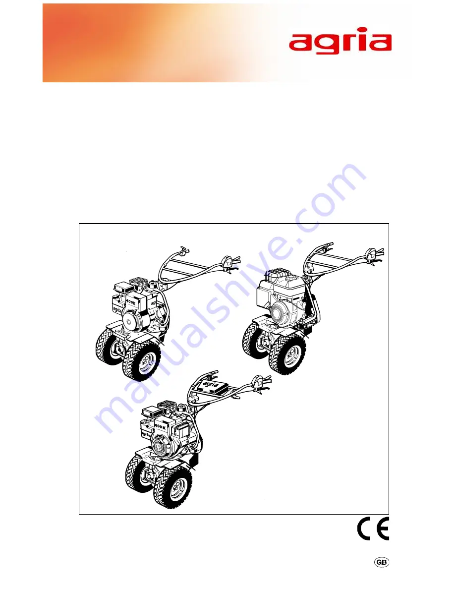
Briggs&Stratton engine

Multi-Purpose Machine

Multi-Purpose Machine

Multi-Purpose Machine

Multi-Purpose Machine

Multi-Purpose Machine

400E and 400K

400E and 400K

400E and 400K

400E and 400K

400E and 400K

Original

Original

Original

Original

Original

Operating

Operating

Operating

Operating

Operating

Instructions

Instructions

Instructions

Instructions

Instructions

3348, 5117, 3346

Summary of Contents for 400E

Page 1: ...n engine Multi Purpose Machine Multi Purpose Machine Multi Purpose Machine Multi Purpose Machine Multi Purpose Machine 400E and 400K 400E and 400K 400E and 400K 400E and 400K 400E and 400K Original Original Original Original Original Operating Operating Operating Operating Operating Instructions Instructions Instructions Instructions Instructions 3348 5117 3346 ...

Page 2: ...imen sions stated in these instructions are not binding No claims can be derived from them We reserve the right for improvements without changing these instructions Amount of delivery l Operating instructions l Grassland mower basic machine l Steering handle with grip screw l Tool kit version 400K additionally l Starter battery with battery acid Symbols Warning Danger Important information Fuel Ch...

Page 3: ...agria Multi Purpose Machine 400E 400K 3 Designation of Parts Type 400E A B Version Briggs Stratton 5 HP 135 202 Version Briggs Stratton Power Built 190 110 412 ...

Page 4: ...ransmission oil drain opening 8 Pto pto guard 9 Name plate machine identification no 10 Handlebar 11 V belt guard V belt clutch 12 Drive wheel 13 Drive wheel detent spring 14 Guard Figure B 1 Air filter 2 Carburetor 3 Fuel tank cap 4 Fuel tank 5 Choke lever 6 Engine type no 7 Starter handle 8 Cooling air screen 9 Exhaust with guard 10 Spark plug spark plug connector 11 Engine oil filler plug and c...

Page 5: ...ve wheels 26 30 Pto 31 Stand 31 Steering handle 32 Battery 33 Attachments 34 37 Hoeing ridging 38 40 4 Commissioning and Operation Commissioning the machine 41 Starting the engine 42 Switching off the engine 43 Working 44 Danger zone 44 5 Maintenance Engine 400E 400K 45 46 Air filter 47 Fuel system 47 Cooling system 48 Spark plug 48 Governor 48 Exhaust 48 Speed Control 49 Carburetor settings 49 Ba...

Page 6: ...6 agria Multi Purpose Machine 400E 400K ...

Page 7: ...agria Multi Purpose Machine 400E 400K 7 C D Designation of Parts Type 400K ...

Page 8: ...pening 8 Pto pto guard 9 Name plate machine identification no 10 Handlebar 11 V belt guard V belt clutch 12 Drive wheel 13 Drive wheel detent spring 14 Guard Figure D 1 Air filter 2 Carburetor 3 Fuel tank cap 4 Fuel tank 5 Choke lever 6 Engine type no 7 Starter handle 8 Cooling air screen 9 Exhaust with guard 10 Spark plug spark plug connector 11 Engine oil filler plug and dip stick 12 Engine oil ...

Page 9: ...e of the battery and the acid should be at least 10 C l Place the battery in the battery holder 5 and tighten down using the tensioning spring 6 place over the battery and insert the hook into the hole A and ensure that the protective hose 7 is located in the area of the battery terminals l Connect the battery cable first connect the posi tive terminal to the red cable then the negative terminal t...

Page 10: ...leaded regular and supergrade petrol as well as on leaded supergrade petrol Do not add oil to petrol If for environmental reasons you use unleaded petrol make sure the fuel is drained completely when shutting down the engine for more than 30 days This is to prevent resin residue from deposit ing in the caburetor fuel filter and tank Or add a fuel stabilizer to the fuel For further instructions see...

Page 11: ...opera tion maintenance and repair Any unauthorized changes to the ma chine render manufacturer liability null and void General Instructions on Safety and Accident Prevention Basic Rule The respective national accident preven tion regulations have to be adhered to as well as all other generally accepted rules governing operational safety oc cupational health and road traffic regu lations When drivi...

Page 12: ...cy Ensure that all guards in place With no attachment mounted make sure PTO shaft is covered with the pro tective cap Starting the engine Do not start the engine in closed rooms The carbon monoxide contained in the exhaust fume is extremely toxic when inhaled Before you start the engine set all con trols to neutral or idling position When starting the engine do not step in front of the machine and...

Page 13: ...s while coupling attach ments Couple the attachments as specified and only couple at specified points Secure the machine and attachment against unauthorized use and rolling off when you leave the machine If neces sary install transport or safety devices to provide protection Hoeing Attachment Adjust the guards in such a way that only the sets of blades penetrating the soil are not covered When hoe...

Page 14: ...e Fuel and Oil Never let the engine run in closed rooms Extreme danger of intoxication For the same reason also replace damaged exhaust pipes immediately Be careful when dealing with fuel Great danger of fire Never refill fuel close to open fire inflammable sparks or hot engine parts Do not refill fuel in closed rooms Do not smoke when refilling Refill only with the engine switched off and cooled ...

Page 15: ...plastic cover if equipped to recharge battery and to prevent highly explosive gases from building up Careful when handling battery acid Only use specified circuit breakers If the circuit breakers are to strong they will destroy the electrical system danger of fire Always cover positive terminal with the specified cover or terminal cap Persons having a pacemaker may not touch live parts of the igni...

Page 16: ...y approx 0 5 l Speeds 2 forward speeds moving V belt to another pulley 1 reverse speed friction wheel see table below Steering handle vibration damping height adjustable side adjustable without tools Weight Approx 44 kg Noise level In accordance with DIN EN 709 and DIN EN 1553 Emission noise level 83 dBA at operator s ear Vibration acceleration value on handlebar ahw 2 5 m s2 in accordance with DI...

Page 17: ...without problems the engine perform ance is satisfactory engine oil level at max upper filling mark 2 Specifications Type 400E Engine pay attention to model type Manufacturer Briggs Stratton 5 HP Type 135 202 0271 Version Fan air cooled 1 cylinder 4 stroke engine petrol Cubic capacity 205 ccm Output 3 2 kW at 3600 rpm Torque max 10 0 Nm at 3000 rpm Spark plug Champion RJ 19 LM Spark plug gap 0 75 ...

Page 18: ...running clutch on drive wheels Transmission oil SAE 90 API GL5 Filling quantity approx 0 5 l Speeds 3 forward speeds moving V belt to another pulley 1 reverse speed friction wheel see table below Steering handle vibration damping height adjustable side adjustable without tools Weight Approx 50 kg Noise level In accordance with DIN EN 709 and DIN EN 1553 Emission noise level 83 dBA at operator s ea...

Page 19: ...long as the operator is able to walk and drive the power mower on slopes without problems the engine perform ance is satisfactory engine oil level at max upper filling mark 2 Specifications Type 400K Engine Manufacturer Briggs Stratton Type 133 237 0136 Version Fan air cooled 1 cylinder 4 stroke engine petrol Bore 65 mm Stroke 62 mm Cubic capacity 205 ccm Output 3 2 kW at 3600 rpm Torque max 10 0 ...

Page 20: ... engine to maximum power Even after the break in period never use engine at higher speed than necessary for the work in hand I High engine speed is harmful to any engine and consider ably affects its durability This applies especially for no load operation Any overspeed have the engine roar can result in immediate damage Cooling System Cooling system is fan cooled Therefore keep screen at recoil s...

Page 21: ...witch serves as emengency off switch In a situation which requires a fast stop move the lever to position STOP Safety Circuit The multi purpose machine is equipped with a safety switch Stop position When releasing the lever E 3 or G 3 the ignition system is switched off engine is cut out Be ware engine keeps running due to centrifugal mass Start position For starting the engine and for short break...

Page 22: ...belt clutch with integrated reverse shift Operation is via the hand clutch lever E 4 or G 4 The machine is decoupled when the hand clutch lever is pulled until the pawl locks into place Now the engine stops driving the machine The decoupled hand clutch lever can be locked with the pawl E 5 or G 5 To avoid clutch slipping away during operation a clutch play is factory set at the hand lever refer to...

Page 23: ...therwise clutch problem may arise due to deformation of V belt Speeds To change speeds you move the V belt to another idler pulley F 12 or H 12 see fold out page 62 or 66 W Before you move the V belt stop the engine and remove the spark plug connector l Remove nut F 10 or H 10 to remove the belt guard F 8 or H 8 and the belt guide plate F 7 or H 7 l Lock the hand clutch lever E 4 or H 4 in neutral...

Page 24: ...en transport work 3 Devices and Operating Elements 3 Type 400K Figure V belt is in speed I position On the V belt guard to the left there is a small window to monitor the current speed i e on which pulley the belt is currently running Recommended speeds Type 400K I Pto driven rotarysnowcleaner attachments mowing sweeping spreading shredding spraying ploughing II Grounds care snow dozing not pto dr...

Page 25: ...lever E 11 or G 11 down to unlock the pawl Wheel drive disengaged Move wheel drive lever E or G 11 up to lock the pawl With the engine running the wheel drive is engaged the following way l Pull the hand clutch lever E 4 or G 4 to middle position neutral and hold l Unlock pawl E 10 or G 10 l Move hand lever for wheel drive E 11 or G 11 down l Slowly release the hand clutch lever E 4 or G 4 while p...

Page 26: ...ith detent spring en gaging into inner ring groove the drive wheel engages with a toothed wheel on the wheel shaft to be driven by the same Mounting drive wheels I For full tractive power mount field tyres with the tread profile pointing in travel direction seen from above l Lift detent spring 1 slightly and place into assembly position fig J front ring groove on hub l Mount drive wheels onto whee...

Page 27: ...grooves fig K If detent springs do not engage turn drive wheels slightly and push them axially inwards until you feel toothed clutch wheel engage l Neutral Push both drive wheels out wards and lock detent springs into outer ring groove fig L l Drive with differential effect En gage one drive wheel into inner ring groove fig K engage the second drive wheel into outer ring groove fig L neutral K L ...

Page 28: ...and anti wind on pipes without tools Twin Wheels l Dismount single drive wheels l Mount twin wheels onto wheel shaft as described in Mounting Drive Wheels l Fit special anti wind on pipes onto wheel shaft of twin wheels ensure that valves fit into recesses l Mount single drive wheels onto full dog points of twin drive wheels Cage Drive Wheels l Dismount drive wheels l Mount cage drive wheels onto ...

Page 29: ...ilitate steering and turning and are used for ploughing and mowing Fit the differential hubs Push the differential hubs 2 on the wheel shaft l Insert the hex bolts 4 together with the star washers 3 into the borings of the hub pipe and wheel shaft and tighten at a torque of 80 Nm l Use wheel bolts 7 and ball spring washers 6 to fit the drive wheels to the differential hubs torque of wheel bolts is...

Page 30: ... hub and fit the locking collar l Use a grease gun to lubricate wheel flange nipple 3 with Bio grease after every 50 operating hours or after pres sure cleaning Wheel weights Drive wheels 4 00 8 with differential hubs can be fitted with wheel weights Item no 0421 011 Fitting wheel weights To fit wheel weights 2 onto the wheel flange use hex bolts 4 and star wash ers Torque 80 Nm 3 Devices and Oper...

Page 31: ...r sleeve can not lock into drive shaft pin then shortly lift the hand clutch lever E 4 or G 4 all the way to reverse while mov ing the pto lever To do this the engine has to be in neutral not full throttle Stand on Type 400K The 400K model is equipped with a stand on the basic machine which allows the machine to be parked more easily after the attachment has been decoupled To do this push on the s...

Page 32: ...g hole in steering bar joint Steering Handle Type 400K Steering handle height adjustment l Remove the grip screw 2 from the square clamping piece 3 and remove it from the steering bar joint l Adjust the steering handle to the de sired height and fit it into proper boring of the steering bar joint l Insert the grip screw and bolt it down to the clamping piece 3 Ensure that nose of clamping piece 3 ...

Page 33: ...explosion Careful when handling battery acid etching 3 Devices and Operating Elements 400K 3 Only use specified fuses If fuses are too strong the electric system will be destroyed danger of fire Avoid short circuits Power is used from the battery when starting by using the electrical start equipment This causes it to discharge The generator partially re charges it during operation I The battery ma...

Page 34: ...devices Before you couple and decouple the attachment park the ma chine on level ground Coupling l Move pto lever to 0 l Remove cap f from the pto l Rest the attachment on the stand c if equipped l Bring tensioning bands into starting position 1 Move both tensioning levers a to the rear 2 pull both tensioning bands b towards the side while you 3 move both tensioning levers back to the front 3 Devi...

Page 35: ...up and lock It will be easier to move the springs of the tension levers back to their original position if the wheels are in position NEUTRAL see chapter Wheel drive on page 27 Decoupling To decouple the attachment reverse the above process Fit the cap onto the pto shaft of the ba sic machine W Warning Only drive pto driven attach ments at speed I slow Only operate attachments only with all guards...

Page 36: ...hing device 1 optional is an adapter placed between the drawbar coupling and the attachments plough cultivator etc These attachments are placed with their connecting yoke into the connecting collar 2 fixed down using the connecting pin 3 which is then secured with a spring clip 4 The working height with the hitching device may be individually adjusted by using the crank 5 The amount of movement pl...

Page 37: ...ge The bolt serves as a coupling pin to couple the attachment using fast tensioning devices The hex bolt remains in its place when the weight support is removed Fitting the weight support l Fit the weight support to the front at tachment flange with the central quick tensioning device l Push the front weight 2 onto the square pin 1 and squeeze tight with hex bolt 3 Removing the weight support When...

Page 38: ...case l Bolt down sets of blades with hex bolts 7 through the borings of the hub rotor shaft 65 cm hoeing width l To fit the standard sets of blades fol low the instructions for a 45 cm cultivat ing width l Fit the add on sets of blades acces sory No 1008 111 6 in the hubs of the standard sets l Insert linch pins 2 in hub shaft borings to secure them l Bolt down 9 3 1 the guards 4 Guard discs The d...

Page 39: ... soil The deeper the depth bar is pushed into the soil the slower is the machine s forward movement and the blades will cultivate the soil at a greater depth Depth setting deep for heavy hard soil high light loose soil To work on sandy soils turn the depth bar upside down for the angled end to point down and backwards Setting the depth bar l Loosen clamp screw 22 push the depth bar to the desired ...

Page 40: ...down with hex bolt 4 Strake wheels For full tractive power or improved ridg ing in cultivated soil strake wheels Ac cessory no 0120 011 16 can be used instead of blade sets The strake wheels are fitted like the blades by inserting hex bolts into borings of hub and shaft Ridging To use the machine for ridging proceed as described in chapter Hoeing l You readjust the ridging depth by adjusting the r...

Page 41: ...g must sit tight in the oil filler neck To avoid starting problems top up fuel before starting for the first time and af ter longer storage Before each operation l Check the engine oil level fig R if necessary do not add too much oil l Check whether the fuel tank contains enough fuel Do not fill the fuel tank until the fuel over flows Leave enough room approx 5 mm for the fuel to expand W Be caref...

Page 42: ... engine Move the choke lever to position CHOKE Warm engine Do not use the CHOKE operating position Pull the clutch lever and safety circuit shift lever in start position Flick the engine shut off switch to I only version Power Built engine Move the speed control lever to a central position between idling speed and full throttle Start engine with the reverse starter start from a position outside th...

Page 43: ...gine Move the speed control lever to idle position and let the engine run idle min for approx half a minute Flick the engine shut off switch to position 0 Close the fuel tap Withdraw spark plug connector protection against unauthorised use W Have the engine cooled down before parking the power hoe in closed rooms W Do not move the choke lever to CHOKE position to shut off the engine danger of fire...

Page 44: ...ntrol lever to NEUTRAL IDLE POSITION l Pull hand clutch lever E 4 or G 4 to middle position and wait until the machine stops moving forward l Pull hand clutch lever all the way up and press the trottle at the same time W If cleaning becomes neces sary during operation cut out the engine and remove spark plug con nector for safety reasons End of operation l Switch off wheel drive To do this pull ha...

Page 45: ...ller plug l Oil level must level with oil filling opening Fig R l If this is not the case refill engine oil refer to Specifications Do not over fill l Re tighten oil filler plug 5 Maintenance Type 400E R 400E Changing Engine Oil The first oil change is after 5 operat ing hours Following oil changes are after every 50 operating hours or at year ly intervals depending on which oper ating period is c...

Page 46: ...ck into the oil tank Remove dip stick again and read the oil level Fig R l In case the oil level is below the lower mark refill engine oil refer to Specifi cations Do not overfill the tank l Re tighten oil filler plug 5 Maintenance Type 400K Changing Engine Oil The first oil change is after 5 operat ing hours Following oil changes are after 50 operating hours or at yearly in tervals depending on w...

Page 47: ... and press to prevent the dry filter element from becoming wet due to excess oil l Tap dry filter element do not blow clean with compressed air Do not treat with oil l Clean dry filter element after every 100 operating hours or after heavy soil ing Version Power Built engine see separate Briggs Stratton engine operating instructions 5 Maintenance Fuel System l Each time you maintain the machine ch...

Page 48: ...sting equipment 5 Maintenance Cleaning the Cooling Screen After long operation dirt can clogg the cooling system To avoid overheating and damage to the engine regularly clean the cooling screen B 8 or D 8 Check each time before you take up operation Air Cooling System Clean internal cooling fins and surfaces at least every 100 operating hours ear lier in very dusty conditions è Serviceç Governor F...

Page 49: ...ing by using the electrical start equipment This causes it to discharge The generator partially re charges it during operation Use a standard charger with 12V and a maximumchargeof0 6Aforre charging If the machine or trailer will not be used for a longer period the battery must be kept fully charged with a current of 0 06A and checked every 4 weeks and re charged if necessary Before recharge disco...

Page 50: ... wheels once a year and after clean ing with a pressure washer l Check transmission oil level before you take up operation and after every 25 operating hours l Park machine on level ground fig V and re move oil filler plug 1 l Oil level must reach filling opening Refill trans mission oil if necessary l Re tighten oil filler plug Exchange transmission oil once per year while the engine is still war...

Page 51: ...y re adjust espe cially after commissioning the machine during break in period and after exchanging clutch V belt l Remove the retaining spring 2 with a screw driver or similar tool l Remove cable end 3 and set pin 4 out of bracket in hand lever l Adjust the set pin 4 to a play of X Screw set pin in to reduce play screw out to increase play l Place cable end and set pin back into bracket and check...

Page 52: ...f pawl E 5 or G 5 is locked l Screw V belt pulley and rubber pul ley II into wall until V belt tension is normal for reverse speed l Prepare rubber pulley II for reverse speed by adjusting the Bowden cable in the hand clutch lever fig X in such a way that the space between the outside diameter of pulley I and the outside diameter of rubber pulley II is 5 mm fig Y l Engage hand clutch lever for for...

Page 53: ... lubricating grease and Bio slushing oil Cleaning Machine After cleaning the machine with a pres sure washer lubricate all lubrication points immediately and let the machine run for a short time to press water out Apply grease generously to leave a grease ring around bearings to prevent water plant sap and dirt from penetrat ing Engine Clean the engine only with a cloth Avoid spraying with strong ...

Page 54: ...rip until resist ance is felt valves are closed l Slowly crank the engine after every 2 3 weeks spark plug connector is re moved Then set the piston to compres sion again c Drive wheels Support drive wheels in such a way that tyres have no ground contact Pneu matic tyres are quickly destroyed if left standing under load and unsupported d Clutch Always park the machine with the hand clutch lever pu...

Page 55: ...agria Multi Purpose Machine 400E 400K 55 5 ...

Page 56: ...e firmly connect spark plug connector to spark plug Clogged fuel line or poor fuel Clean fuel line fill fresh fuel 41 Vent opening in fuel tank cap clogged Exchange fuel tank cap Water or dirt in fuel system Drain fuel and fill fresh fuel Air filter clogged Clean air filter or exchange 47 Carburetor misadjusted Re adjust carburetor 49 Excessive Low engine oil level Refill oil immediately 45 46 tem...

Page 57: ...or Tighten cylinder head 49 damaged sealing exchange sealing Poor compression Have engine checked Travelling drive Incorrect hand clutch lever adjustment Adjust hand clutch lever 51 or mowing drive does not stop with clutch pulled Excessive Fastening screws loosened Tighten fastening screws 53 vibration For this purpose contact your agria workshop 6 Troubleshooting 6 ...

Page 58: ...e 2 Magnet ignition system 3 Engine off switch on speed control lever next to engine 4 Connector pair 5 Switch in safety lever 6 Switch in clutch lever bl blue br brown Lubrication chart 1 Engine oil page 45 46 2 Transmission oil page 50 3 Lever bearing page 53 3 2 1 ...

Page 59: ...n 400ml 712 98 Spray varnish red RAL 2002 spray tin 400ml 509 68 Spray varnish black spray tin 400ml Wear Parts 672 44 Air filter insert 686 34 Spark plug RJ 19 LM 481 75 V belt for clutch 481 74 V belt for reverse drive 305 65 Gasket for housing cap oil change Note Only use original agria V belts Spare Parts 997 086 All purpose machine 400E 400K and attachments Varnishes Wear Parts 771 83 Suction...

Page 60: ...60 agria Multi Purpose Machine 400E 400K ...

Page 61: ...f switch 10 Pawl for wheel drive lever 11 Hand lever for wheel drive 12 Engine shut off switch only version Power Built engine Figure F 1 Idler pulley 2 Drive V belt for forward speed clutch 3 Vibration damper 4 Threaded pin for belt guard 5 Borings for threaded pins 6 V belt pulley on crank shaft 7 Belt guide plate 8 Belt guard 9 Spring washer 10 Lock nut 11 Reverse rubber pulley 12 Drive V belt ...

Page 62: ...62 agria Multi Purpose Machine 400E 400K E F Designation of Parts Type 400E ...

Page 63: ...agria Multi Purpose Machine 400E 400K 63 ...

Page 64: ...ling screen K 48 Check engine oil level refill if necessary K K 45 46 Re tighten cylinder head screws E 49 First engine oil change W 45 subsequent oil changes W 46 Clean engine K 53 Check transmission oil level K 50 Check bolts and nuts K 53 Clean air filter insert W W 47 Lubricate differential hub K K K 30 Replace air filter insert earlier if required W 47 Clean spark plug adjust gap W 48 Replace...

Page 65: ...h lever 6 Pto speed lever 7 Tool kit 8 Starter switch 9 Speed control lever engine off switch 10 Pawl for wheel drive lever 11 Hand lever for wheel drive Figure H 1 Idler pulley 2 Drive V belt for forward speed clutch 3 Vibration damper 4 Threaded pin for belt guard 5 Borings for threaded pins 6 V belt pulley on crank shaft 7 Belt guide plate 8 Belt guard 9 Spring washer 10 Lock nut 11 Reverse rub...

Page 66: ...66 agria Multi Purpose Machine 400E 400K G H Designation of Parts Type 400K ...

Page 67: ...agria Multi Purpose Machine 400E 400K 67 EC Declaration Conformity ...

Page 68: ...agria Werke GmbH Bittelbronner Straße 42 D 74219 Möckmühl Tel 49 0 6298 39 0 Fax 49 0 6298 39 111 e mail info agria de Internet www agria de Your local agria specialist dealer ...

Reviews: