background image

StudioStar

Owner’s Guide


Preface

This chapter gives you information about StudioStar™ and about the organization of this
Owner's Guide.


Chapter 1 — Preparing the scanner

It shows you how to prepare your StudioStar for installation.


Chapter 2 — Installing the scanner

“Installing the scanner” instructs you how to set up your StudioStar for the Apple®

Macintosh® and for PC™.


Chapter 3 — Using the scanner

Chapter 3 shows you how to place your originals.


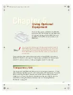
Appendix A — Using the transparency option

This appendix gives you instructions on how to connect the transparency option you may
have purchased.


Appendix B — Using the document feeder option

In this appendix you can read how to connect the document feeder option you may have
purchased.


Appendix C — Troubleshooting

“Troubleshooting” can be helpful when you come across problems that you are unable to
solve.


Appendix D — Technical information

This appendix provides technical specifications for your StudioStar.


Appendix E — Regulation compliance

It gives you information about safety regulations and electromagnetic interference.

ab

c

The complete picture.

Summary of Contents for StudioStar

Page 1: ...Appendix A Using the transparency option This appendix gives you instructions on how to connect the transparency option you may have purchased Appendix B Using the document feeder option In this appendix you can read how to connect the document feeder option you may have purchased Appendix C Troubleshooting Troubleshooting can be helpful when you come across problems that you are unable to solve A...

Page 2: ... is a registered trademark of Caere Corporation System 7 is a trademark and Apple and Macintosh are registered trademarks of Apple Computer Incorporated Windows is a trademark of Microsoft Corporation Other product or company names are trademarks or registered trademarks of their respective holders Copyright 1996 Agfa Gevaert N V All rights reserved All software and hardware described in this docu...

Page 3: ...ation for the Apple Macintosh 16 Choosing a SCSI ID number 16 Connecting the scanner 18 Testing the connection 21 Installation for the PC 22 Which SCSI interface card 22 Choosing a SCSI ID number 24 Connecting the scanner 26 Testing the connection 30 Installation of the software 30 3 Using the scanner 3 1 Placing reflective originals 31 Placing reflective originals in your document feeder option 3...

Page 4: ... the document feeder option 43 Paper loading 44 Correcting paper jams 45 Maintaining the document feeder option 46 Cleaning and replacing the guide flap 46 Roller cleaning 46 Appendix C Troubleshooting 47 Appendix D Technical information 49 StudioStar specifications 49 Transparency option specifications 50 Document feeder option specifications 50 Appendix E StudioStar regulation compliance 52 ...

Page 5: ...oduce even the most difficult originals StudioStar s image quality makes it suitable for pre press graphical applications It is based on flatbed CCD scanning technology StudioStar is characterized by a large input size range and a high scanning speed Due to its 5 000 CCD pixels an impressive output size range can be achieved This high precision instrument features exceptional sharpness and color f...

Page 6: ...the plastic wrapping and the packing materials from the scanner Note Save the packing materials so that you can repack the scanner to protect it if you have to move it over long distances 4 Fill out the Warranty and Registration card of your scanner You will find the product serial number on it You will have to fill out extra Warranty and Registration cards if you acquired the transparency option ...

Page 7: ... scanner 1 Place the scanner on a horizontal flat surface and pull it forwards until you can see the carriage lock on the underside 2 Remove the piece of Styrofoam 3 Press in the detent on the side of the carriage lock 4 Push the carriage lock up The carriage lock comes loose Your scanner is unlocked 5 Move the scanner back on your desktop Allow a minimum of 10 cm 4 free space around each side of ...

Page 8: ...er s optical assembly from possible damage 1 Place the scanner on a horizontal flat surface and pull it forwards until you can see the carriage lock on the underside 2 Turn on your scanner The scanner s optical assembly moves to its home position 3 When the ready indicator the middle yellow one stops blinking pull the carriage lock down Your scanner is locked 4 Switch off your scanner ...

Page 9: ... the scanner 9 Taking a closer look Now that you have the scanner out of the box take a closer look so that you become familiar with its parts The figures illustrate the locations of the different parts of your StudioStar ...

Page 10: ...over 3 rulers 4 power indicator green 5 ready indicator yellow 6 transparency indicator yellow 7 power switch 1 power connector 2 25 pin SCSI connector 3 50 pin SCSI connector 4 female DB 15 pin connector for connecting the transparency option or the document feeder option ...

Page 11: ...ble check whether the voltage indicated on the back panel of the scanner corresponds with the voltage in your area If not call your dealer 3 Switch on the scanner The power indicator green lights up and the ready indicators flash briefly The scanning lamp turns on The scanner performs a self test after which the ready indicator the middle yellow one switches on This takes about 15 seconds or less ...

Page 12: ... Connecting the scanner Testing the connection Installation of the software Minimum hardware requirements and recommendations For the Apple Macintosh n A 68020 processor n A 13 color monitor n A 24 bit video card for an accurate display of color images n 5 Mb of RAM 8 Mb recommended n A high capacity disk drive n System 7 0 or higher n The amount of disk space available on your Macintosh determine...

Page 13: ...SCSI interface card n The amount of disk space available on your PC determines the number and the size of the images you can scan Make sure you have enough free storage space on your hard disk You need about two times the size of the image to scan edit and save it You need minimum 30 Mb free hard disk space and 8 Mb of RAM for color images Environmental requirements Place the scanner on a horizont...

Page 14: ...plate and when the scanner needs service or repair Do not open the scanner housing as it contains high voltage areas and sensitive components Any curative maintenance should be carried out by your dealer Do not leave originals on the reflective glass plate or on the slide holder frame for excessive periods of time The warmth of the scanner may cause them to deteriorate To avoid crashes never use e...

Page 15: ...our computer to identify the device it wants to communicate with and the priority of each device A SCSI chain requires an electronic component called a terminator which absorbs old signals traveling along the cables and keeps the path open for new signals The chain should never have more than two terminators one at each end It is important to remember that using too many or too few terminators may...

Page 16: ... find out which SCSI ID numbers are already assigned and which numbers are free To do this you can use the Macintosh utility SCSI ID Checker You will find this utility in the FotoLook folder after you installed the software 1 Copy the SCSI ID Checker to your Macintosh computer if not already done 2 Open the SCSI ID Checker A dialog box appears with a list of the SCSI ID numbers that are free in yo...

Page 17: ...gned you need to set the scanner to a free SCSI ID number 1 Make sure your scanner is switched off and is disconnected from your computer 2 Decide on an unassigned SCSI ID number 3 Push above or underneath the SCSI ID number until you see the number you want Push above the SCSI ID number to decrease the number push underneath the SCSI ID number to increase the number 4 Click OK to close the SCSI I...

Page 18: ...at the beginning and one at the end Some SCSI devices have built in terminators and must therefore be placed at the beginning or end of your SCSI chain Please check the documentation of each of your SCSI devices if you are not sure whether the device has a built in terminator Your StudioStar has no built in terminator If your StudioStar is the only SCSI device to be connected to your Apple Macinto...

Page 19: ...emove the terminator from the last device in the SCSI chain 2 Connect the 50 pin end of the SCSI cable to the connector that has become available on this device 3 Place the terminator on the free 50 pin connector of the scanner 4 Connect the 25 pin end of the SCSI cable to the free connector of the scanner 5 Snap the diamond shaped wire clips into the clip brackets to secure the connection ...

Page 20: ...s 2 Connect the free end of this SCSI cable to the scanner 3 Connect the 50 pin end of the SCSI cable the one supplied with your scanner to the other adjacent SCSI device 4 Connect the 25 pin end of the SCSI cable the one supplied with your scanner to the scanner 5 Snap the diamond shaped wire clips into the clip brackets to secure the connection ...

Page 21: ... self test after which the ready indicator the middle yellow one switches on This takes about 15 seconds or less If a malfunction is detected during the self test that is if the ready indicator remains off refer to Appendix C Troubleshooting 4 Switch on any other SCSI devices you may have attached and wait for them to start up 5 Switch on your Macintosh As it starts up your Macintosh performs a se...

Page 22: ...anner Testing the connection Which SCSI interface card StudioStar requires a SCSI interface card for example the Adaptec card AVA 1502P that is supplied with the scanner to work with your PC PC AT 386 486 or compatible computer If your PC does not have such a card you have to install the SCSI interface card that is supplied with your scanner 1 Remove the chassis cover of your computer 2 Locate an ...

Page 23: ...formation about the installation of the SCSI card please refer to the documentation on the AGFA scanner CD ROM If your PC already has a SCSI interface card you can extend your network The scanner software supplied with StudioStar supports ASPI compatible SCSI interface cards Note Please check the following documentation The Read Me file on the PC scanner driver software disk for up to date informa...

Page 24: ...en the SCSI ID checker utility A dialog box appears with a list of the SCSI ID numbers that are free in your PC Your PC always occupies ID 7 If your PC is equipped with 2 SCSI busses the button Next Bus allows you to switch busses 2 Check if SCSI ID number 2 is free Your StudioStar is preset to ID 2 3 If SCSI ID number 2 is free close the SCSI ID checker utility If SCSI ID number 2 is already assi...

Page 25: ...er 25 3 Push above or underneath the SCSI ID number until you see the number you want Push above the SCSI ID number to decrease the number push underneath the SCSI ID number to increase the number 4 Close the SCSI ID checker utility ...

Page 26: ...nect the scanner to the serial or parallel port of your PC you might seriously damage your equipment if you do If your PC has a high density SCSI connector you might need to buy a special cable from your dealer If your PC has a 25 pin connector follow the instructions of Installation for the Apple Macintosh Connecting the scanner If your PC has a 50 pin connector and your StudioStar is the only SC...

Page 27: ...Chapter 2 Installing the scanner 27 ...

Page 28: ...t the scanner to an unused SCSI ID number between 1 and 6 For more information see Choosing a SCSI ID number earlier in this chapter 2 Connect the 50 pin end of the SCSI cable to the connector at the rear of your device 3 Place the terminator on the 50 pin connector of the scanner Snap the diamond shaped wire clips into the clip brackets to secure the connection 4 Connect the 25 pin end of the cab...

Page 29: ...anner to an unused SCSI ID number between 1 and 6 For more information see Choosing a SCSI ID number earlier in this chapter 3 Connect the 50 pin end of the SCSI cable to the connector at the rear of the adjacent device 4 Connect the 25 pin end of the cable to the scanner s 25 pin connector 5 Connect the scanner to the next device in the SCSI chain 6 Make sure that the last device in the chain is ...

Page 30: ...est after which the ready indicator the middle yellow one switches on This takes about 15 seconds or less If a malfunction is detected during the self test that is if the ready indicator remains off refer to Appendix C Troubleshooting 4 Switch on any other SCSI devices you may have attached and wait for them to start up 5 Switch on your PC 6 Check in Show SCSI if the SCSI interface card sees the s...

Page 31: ...original on the glass plate with its image side down and with its top side against the middle of the front ruler Optical performance of a CCD scanner is always best near the middle of the glass plate 3 Lower the document cover of the scanner The adjustable document cover makes it possible to scan from books and magazines when you put a thicker original on the reflective glass plate the document co...

Page 32: ...on 3 Place the original that you want to scan on the glass plate with the emulsion down and with its top side towards the calibration slit This position guarantees the best quality Make sure that the calibration slit in the frame is at the front side standing in front of the scanner and that it is free To see where the calibration slit is situated you have to use the template that is delivered wit...

Page 33: ...e first thing to do is to make sure you have everything you are supposed to 1 Open the packing box and take out all the items 2 Check each item to make sure that you have everything and that there is no visual defect If something is missing contact your dealer 3 Remove the plastic wrapping and the packing materials from the transparency option 4 Fill out the Warranty and Registration card You will...

Page 34: ...of the transparency option 2 Turn the hand screw clockwise Your transparency option is unlocked Connecting the transparency option 1 Check if your scanner and your transparency option are properly unlocked 2 Turn off your scanner 3 Turn off your computer 4 If the document feeder option is installed disconnect it from your scanner 5 Place the transparency option as shown in the figure ...

Page 35: ...Appendix A Using the transparency option 35 6 Lower the transparency option ...

Page 36: ... to the female DB 15 pin connector at the rear of the scanner 8 Place the template that came with your transparency option on the glass plate as shown in the figure Caution Make sure that the clear opening rectangle of the template faces the front of the scanner and is not covered by the transparent originals ...

Page 37: ...Appendix A Using the transparency option 37 The transparency option is ready for use 9 Turn your scanner on 10 Turn your computer on ...

Page 38: ...Document Feeder is a companion sheet feeder for your StudioStar It allows automatic scanning of up to 10 sheets The dimension of the document can be as large as 8 5 x 14 Sheets to be scanned are fed from a stack in the ADF s input tray guided past the scanner s image sensor and placed in the feeder s output tray The ADF mounts onto the scanner in place of a document cover using the original docume...

Page 39: ...rear of your document feeder option Note Save the packing materials so that you can repack the document feeder option to protect it if you have to move it over long distances Before you begin Follow these steps before installing the ADF 1 Install the scanner as described in this Owner s guide 2 Make sure that the scanner its peripherals and the computer are all powered off Unplug the scanner s pow...

Page 40: ...Appendix B Using the document feeder option 40 ...

Page 41: ...connector at the rear of the scanner Secure the connector by tightening its retaining screws 8 After the ADF is securely attached swing the paper support up to over 60 degrees The paper support should stay in the raised position by itself 9 Press the locking button at the right side of the ADF The upper housing of the ADF popes up a little ...

Page 42: ...Appendix B Using the document feeder option 42 10 Raise the transportation module ...

Page 43: ...de flap 12 Close the ADF 13 Turn your scanner on 14 Turn your computer on Software like OmniPage Limited Edition makes it possible to convert the scanned sheets of text into most of the commercially used text file formats Operating the document feeder option When the ADF is installed and the computer and the ADF are powered on start up the scanner application software ...

Page 44: ...s not scanned documents will jam up against the base of the feeder rather than being moved into the output tray To load documents 1 Pull the paper support up this prevents the paper sheets not to bend down 2 Place the documents in the input tray with the side to be scanned facing down 3 Make sure the pages are aligned in the center with the two guide arms 4 If the documents are less than 8 5 wide ...

Page 45: ...s To remove jammed pages 1 Press the ADF locking button The ADF transportation module is disengaged 2 Lift the transportation module then grasp both free corners of the jammed sheet and pull it out slowly 3 Lower the ADF transportation module down and snap to close it ...

Page 46: ...he surface of the flap may become scratched This causes lines to appear in scanned images that can create OCR errors Should the scratches appear detach the flap and replace it by a new one For a new guide flap please contact your dealer Roller cleaning Prolonged use of the ADF may result in accumulation of ink and other contaminants on the feeder s input roller reducing the roller s efficiency Che...

Page 47: ...t your dealer The scanner or Transparency option lamp flickers dims or fails to come on The scanning lamp is failing or has failed and needs to be changed Contact your dealer The scanner driver software returns a Scanner not ready or similar message Verify the power connection to the scanner Check that the power switch is turned on Check the Installation procedure to see if you followed the instru...

Page 48: ...nect all SCSI devices except the start up disk and connect them one by one beginning with the scanner to identify the device that causes the problem switch all devices off before breaking or making connections The scanner software cannot find the scanner After opening the Scan dialog box a message appears telling that no scanner is connected although the scanner is connected Check the Installation...

Page 49: ...ass Maximum resolution optical 600 dpi horizontal x 1200 dpi vertical through interpolation 2400 dpi horizontal x 2400 dpi vertical Sample depth 10 bits for gray 30 bits for colour Scanning speed line art 5 ms per line halftone 5 ms per line gray 5 ms per line colour 6 5 ms per line Maximum scanning area 211 mm x 355 mm 8 5 x 14 Lamp cold cathode Warm up time 15 seconds Power supply line voltage 1...

Page 50: ...m x 252 mm 8 x 10 Lamp cold cathode Power supply from the scanner Interface 15 pin cable with connector to scanner Dimensions length width 515 54 mm 20 328 54 mm 13 height 57 55 mm 2 weight 4 7 kg 10 lb Environment operating temperature 10 C to 40 C 50 F to 104 F relative humidity 20 to 85 surrounding space 10 cm 4 on each side 15 cm 6 at the rear side Document feeder option specifications Capacit...

Page 51: ...8 42 input tray height 77 mm 3 03 Dimensions length 435 mm 17 height 77 mm 3 weight 2 3 kg 5 0 lb Power supply from the scanner Operating conditions temperature 10 C to 40 C 50 F to 104 F relative humidity 20 to 80 Note Technical specifications are subject to change without notice ...

Page 52: ...ntioned in this operation manual don t try to remove any mechanical parts or any electronic devices If you need service our dealer and service offices are available to help you FTZ Bescheinigung des Herstellers Importeurs Hiermit wird bescheinigt dass der Image Scanner in Übereinstimmung mit den Bestimmungen der vgf 1046 1984 funk entstört ist Der Deutschen Bundespost wurde das inverkehrbringen di...

Page 53: ... and found to comply with the limits for a Class B digital device pursuant to Part 15 of the FCC Rules These limits are designed to provide reasonable protection against harmful interference when the equipment is operated in a residential installation This equipment generates uses and can radiate radio frequency energy and if not installed and used in accordance with the instruction manual may cau...

Page 54: ...from digital apparatus set out in the Radio Interference Regulations of the Canadian Department of Communications Le présent appareil numérique n émet pas de bruits radioélectriques dépassant les limites applicables aux appareils numériques de la classe B prescrites dans le Règlement sur le brouillage radioélectrique édicté par le ministère des Communications du Canada ...

Reviews: