background image

Mess-, Regel- und 
Überwachungsgeräte 
für Haustechnik, 
Industrie und Umweltschutz 


Lindenstraße 20 
74363 Güglingen 
Telefon  +49 7135 102-0 
Service  +49 7135-102-211 
Telefax  +49 7135-102-147 
[email protected] 
www.afriso.de 


Read instructions before using device! 


Observe all safety information! 


Keep instructions for future use! 

 
12.2013 0 
854.001.0692 


Operating instructions 

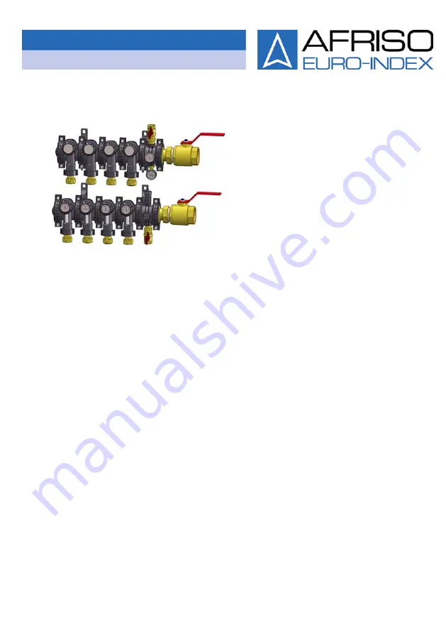
Brine / heating circuit manifold 
ProCalida

®

 GT 3 

# 81704 


Summary of Contents for ProCalida GT 3

Page 1: ...ingen Telefon 49 7135 102 0 Service 49 7135 102 211 Telefax 49 7135 102 147 info afriso de www afriso de Read instructions before using device Observe all safety information Keep instructions for future use 12 2013 0 854 001 0692 Operating instructions Brine heating circuit manifold ProCalida GT 3 81704 ...

Page 2: ...lication examples 9 4 Technical specifications 11 4 1 Charts 13 5 Mounting and commissioning 18 5 1 Mounting the heating circuit connections 18 5 2 Pre assembling the brine heating circuit manifold 19 5 3 Mounting the brine heating circuit manifold with wall brackets to the wall 21 5 4 Mounting the brine heating circuit connection 22 5 5 Filling flushing and venting the system 24 5 6 Performing th...

Page 3: ...n here There are three different levels of warnings Warning term Meaning DANGER Immediately imminent danger Failure to observe the information will result in death or severe injuries WARNING Possibly imminent danger Failure to observe the information may result in death or severe injuries CAUTION Dangerous situation Failure to observe the information may result in minor or severe injuries as well ...

Page 4: ...and is made ac cording to the pertinent safety regulations Each device is subjected to a function and safety test prior to shipping Operate the product only when it is in perfect condition Always observe the operating instructions all pertinent local and na tional directives and guidelines as well as the applicable safety regulations and directives concerning the prevention of acci dents 2 4 Staff...

Page 5: ... not be liable for costs or damages incurred by the user or by third parties in the usage or application of this device in particular in case of improper use of the device misuse or malfunction of the connection malfunction of the device or of connected devices The manufacturer or the sales company shall not be liable for damage whatsoever resulting from any use other than the use explicitly permi...

Page 6: ... modular brine heating circuit manifold made of glass fibre reinforced polyamide The heating brine circuits are shut off by means of shut off valves at the flow and control valves at the return All seals and the fastening material are included Fig 1 ProCalida GT 3 V Flow R Return ...

Page 7: ...nt 80 100 with shut off valve and pro tective cover 2 Wall bracket short 9 Manifold segment 80 100 with control valve flow me ter thermometer and protec tive cover 3 Fastener 10 Heating circuit connection 4 Connection element 11 Clamp 5 Multi way union 12 Blind cover 6 Boiler filling and drain valve KFE 1 13 Silicone grease 7 Connection 2 ...

Page 8: ...essories 1 90 elbow 5 Ball valve 2 2 Connection element 30 mm 6 Pressure gauge with mount ing valve 3 Connection element 60 mm 7 Thermometer 4 Quick air vent Shut off valves and control valves The shut off valves and control valves when delivered Valve open Valve closed ...

Page 9: ...n ProCalida GT 3 9 3 2 Application examples Fig 4 ProCalida GT 3 with four segments 100 mm Fig 5 ProCalida GT 3 with nine segments 100 mm Fig 6 ProCalida GT 3 with five segments 100 mm and four connec tion elements 60 mm ...

Page 10: ...ion 10 ProCalida GT 3 Fig 7 ProCalida GT 3 with four segments 100 mm connection two segments from above two segments from below Fig 8 ProCalida GT 3 with nine segments 100 mm and two 90 el bows installation in a shaft ...

Page 11: ... with union nut Possible brine circuit connec tions mm Compression fitting Ø 25 x 2 3 2 5 Ø 32 x 2 9 Ø 40 x 3 7 Test pressure 24 h 30 C Max 6 bar Operating temperature and pressure Max 60 C at 3 bar Number of cooling circuits Max 30 Thermometer 20 C to 40 C 0 C to 60 C 20 C to 60 C Flow meter 2 12 l min 5 42 l min 35 70 l min 60 125 l min ...

Page 12: ...ircuits 2 to 20 Brine heating circuits 2 3 4 5 6 7 8 9 10 11 A mm with segment length 80 mm 320 400 480 560 640 720 800 880 960 1040 A mm with segment length 100 mm 360 460 560 660 760 860 960 1060 1160 1260 Brine heating circuits 12 13 14 15 16 17 18 19 20 n A mm with segment length 80 mm 1120 1200 1280 1360 1440 1520 1600 1680 1760 A mm with segment length 100 mm 1360 1460 1560 1660 1760 1860 19...

Page 13: ... 3 13 4 1 Charts Pressure loss curves valve characteristic Pressure loss curves depending on flow stream and opening angle Pressure loss at flow valve considered p Pressure loss mbar Flow stream kg h Fig 10 Diagram for calculating the flow ...

Page 14: ...Technical specifications 14 ProCalida GT 3 Fig 11 Pressure loss curves with flow meter 2 12 l min ...

Page 15: ...Technical specifications ProCalida GT 3 15 Fig 12 Pressure loss curves with flow meter 5 42 l min ...

Page 16: ...Technical specifications 16 ProCalida GT 3 Fig 13 Pressure loss curves with flow meter 35 70 l min ...

Page 17: ...Technical specifications ProCalida GT 3 17 Fig 14 Pressure loss curves with flow meter 60 125 l min ...

Page 18: ...r caps Connect pipes to the brine heating circuit manifold in such a way that there is no traction pressure or mechanical tension see chapter 4 page 11 Depending on the on site conditions the distances between the wall brackets could be shortened to 400 mm Comply with the maximum distances between the wall brackets and between manifold ends and wall brackets see chapter 4 page 11 5 1 Mounting the ...

Page 19: ...ings 2 Insert connection element into segments 3 Mount the fasteners Hand screw the nuts Mounting optional connection elements 30 mm 60 mm Optional connection elements 30 mm 60 mm increase the distance between two segments by 30 mm 60 mm Connection elements 30 mm 60 mm can be combined to increase the distance between the segments 1 Grease the O rings 2 Insert connection element into segments 3 Mou...

Page 20: ...a blind cover to the end segment 1 Grease the O ring 2 Insert the blind cover into the segment 3 Mount the fasteners Hand screw the nuts Mounting connection segments and end segments to middle segments 1 Grease the O rings 2 Put the segment blocks together ...

Page 21: ...TION Hazard of crushing caused by falling brine heating circuit mani fold Brine heating circuit manifolds consisting of multiple seg ments are heavy Heavy brine heating circuit manifolds may only be mounted with the assistance of several persons 1 Define the position of the brine heating circuit manifold at the wall 2 Hold the brine heating circuit manifold to the wall align it hori zontally and m...

Page 22: ...missioning 22 ProCalida GT 3 3 Drill Ø 10 mm holes 4 Mount the brine heating circuit manifold to the wall using suita ble fixing material 5 4 Mounting the brine heating circuit connection Turn the segments if necessary ...

Page 23: ...t and the compression fitting from the heating circuit connection and place them onto the pipe 2 Connect the pipe and the heating circuit connection and tighten the nut with a tightening torque of 100 Nm 20 Nm 3 Tighten the nuts at the fasteners with a tightening torque of 5 Nm ...

Page 24: ...s to the boiler filling and drain valve KFE of the flow and to the boiler filling and drain valve KFE of the return 3 Open the boiler filling and drain valve KFE of the flow 4 Open the flow valve of the first heating circuit V1 Open the return valve of the first heating circuit R1 5 Close all other valves V2 V R2 R 6 Slowly open the boiler filling and drain valve KFE of the return Fill the system ...

Page 25: ...stem at the boiler filling and drain valve KFE of the flow if required 5 6 Performing the pressure test and the function test 1 Apply 6 bar of pressure to the system for a period of 2 hours max 30 C 2 Perform a leak test after 2 hours The pressure drop must not exceed 0 2 bar 3 Fill the system with the fluid until the operating pressure is reached ...

Page 26: ...il the calculated flow rate W is indicated at the flow meter D 2 Pull the ring to the front to unlock 3 Turn the ring all the way to the mechanical stop of the flow valve 4 Push the ring back to lock 5 Turn the thermometer optional into reading position see chap ter 5 8 page 28 6 Repeat the steps for all other heating circuits 7 Fit the protective cover ...

Page 27: ...e the adjustment valve from fig 10 page 13 4 Pull the ring to the front to unlock 5 Set the adjustment value E at the ring 6 Push the ring back to lock 7 Open the return valve all the way to the mechanical stop 8 Fully open the flow valve 9 Turn the thermometer optional into reading position see chap ter 5 8 page 28 10 Fit the protective cover ...

Page 28: ... or in whole without prior written consent We reserve the right to technical modifications with reference to the specifications and illustrations in this manual 7 Customer satisfaction Customer satisfaction is our prime objective Please get in touch with us if you have any questions suggestions or problems concerning your product 8 Addresses The addresses of our worldwide representations and offic...

Reviews: