


www.aeroplusrc.com
AeroPlus
RC
Copyright
2013
©
All
Rights
Reserved
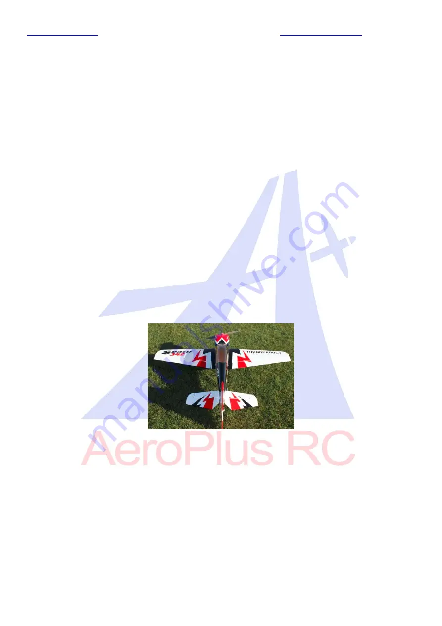
Sbach
342
20CC
Item
No
:
A
‐
G020004
Specifications
Wing
Span
68in(1720mm)
Length
65"(1656mm)
Wing
Area
907sq
in(58.5sq
dm)
Flying
Weight
7
‐
7.7lbs(3200
‐
3500g)
Glow
75
‐
.91
(
2C
)
.91
‐
1.10
(
4C
)
Gasoline
20
‐
26cc
Electric
BRUSHLESS
MOTOR
A5030
Radio
4CH/5
‐
6
servos
Description
Carbon
Fiber
wing
tube,
landing
gear,
tail
gear;
Fibreglass
servo
arms,
horn
and
reinforced
U/C
mounting
Scale
read
deck
Adjustable
pushrods
Ringed
cowl
Pre
drilled
hinges
Colour
schemes
A
‐
G020004A


