manualshive.com logo in svg
background image


AERODIODE - Institut d’optique d’Aquitaine - Rue François Mitterrand 

33400 Talence - France - Tél.: +33 (0)6 27 69 41 62 

www.aerodiode.com


Operating manual 


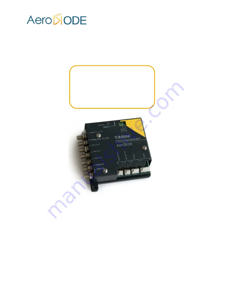
TOMBAK


Pulse Delay Generator 

Digital Delay Generator 

Pulse Picker 

Voltage Converter 

Arbitrary Waveform Generator 


Содержание TOMBAK

Страница 1: ...d Aquitaine Rue Fran ois Mitterrand 33400 Talence France T l 33 0 6 27 69 41 62 www aerodiode com Operating manual TOMBAK Pulse Delay Generator Digital Delay Generator Pulse Picker Voltage Converter...

Страница 2: ...al Delay Generator section 5 2 p33 A burst generator see Using TOMBAK as a burst generator section 5 3 p39 A signal gating module see Using the gate feature of TOMBAK section 5 4 p44 A Synchronization...

Страница 3: ...es 10 4 2 Front Panel overview 11 Power and Communications Connectors 11 SMA Output and Input Connectors 11 KK Connectors 12 4 3 System Setup 12 Power 12 USB 12 Tools Installation Windows 13 4 4 Hardw...

Страница 4: ...erator 33 Presentation 33 Timing diagram 34 Synoptic 34 Cabling 34 Software configuration 35 Main features 38 5 3 Using TOMBAK as a burst generator 39 Presentation 39 Timing diagram 39 Synoptic 39 Cab...

Страница 5: ...g TOMBAK as a frequency divider 60 Presentation 60 Timing diagram 60 Synoptic 60 Cabling 61 Software configuration 61 Main features 64 5 8 Using TOMBAK as a PULSE PICKER 65 Introduction Overview 65 Ti...

Страница 6: ...agrams 72 Software configuration 73 5 11 How to delete the pulse out delay between stacked Tombak 76 Introduction 76 Cabling 77 Software configuration 77 6 Technical Specifications 79 6 1 General Data...

Страница 7: ...on example for AWG Burst shaper V2 0 23 03 2020 Aerodiode transfer V2 1 20 04 2020 Added Safety instruction Layout overhaul V2 2 23 04 2020 Added Specifications Table V2 3 30 04 2020 Added multiple no...

Страница 8: ...y trained personnel 1 1 Definitions Caution A caution is advised when dealing with hazardous situations tasks or objects to prevent harm or death and avoid material damage or failure Warning A warning...

Страница 9: ...e power cord from being walked on or pinched particularly at plugs convenience receptacles and the point where they exit from the TOMBAK module Only use the supplied power and USB cable 2 2 Operating...

Страница 10: ...D ROM or USB Key with Aerodiode Control Software Suite 1 User Manual Figure 1 Package Content Note No SMA cable are supplied Caution This product has been tested and found to comply with the limits ac...

Страница 11: ...Power connector 5V 0 7A Two variants exist either jack Power connector or Terminal Block Only the Terminal bloc variant is displayed in this user manual Input Communication Connector Output Communica...

Страница 12: ...Pulse Input Connector Spare Connectors Factory use only 4 3 System Setup Power To power TOMBAK module please use the DC Power adapter provided First plug the cables into the power connector of the mod...

Страница 13: ...electronic modules and boards 4 3 3 1 Software installation Insert CD ROM or USB Key provided with the module Then open an Explorer windows and navigate into Computer part You will either see a CR ROM...

Страница 14: ...w lets you choose the program s shortcut name in the Start Menu folder Feel free to change it or leave it by default The next part lets you choose if a desktop icon needs to be created If so please ch...

Страница 15: ...9 Finally click on the Install button Installation of the software is now complete To install drivers tools please let all the box checked and click on Finish You can now move to next section Driver...

Страница 16: ...gs and wait until installations are finished 4 4 Hardware Setup Note This chapter is for information only It describes how to change the voltage output digital and anolog of the product You must ask A...

Страница 17: ...ing to the following configuration 1V Jumper J800 in position 2 3 and J801 in position 2 3 5V Jumper J800 in position 1 2 and J801 in position 1 2 4 4 1 3 Sync Ext voltage input level Input maximum vo...

Страница 18: ...2 Shape Out voltage output level Voltage level can be adjusted according to the following configuration 1V Jumper J800 in position 2 3 and J801 in position 2 3 5V Jumper J800 in position 1 2 and J801...

Страница 19: ...Page 19 79 v2 9...

Страница 20: ...K TOMBAK can be delivered in multi channel version with multiple board stacked in a compact module This option allows the user to access multiple output signal while sharing the same power source the...

Страница 21: ...ule and should be connected at the bottom Synchronization signals o SyncOut1 SyncOut2 Synchronization output signals can support multiple signals such as output pulse delayed pulsed internal trigger s...

Страница 22: ...dules Note The lowest line is always the bottom board and the highest line the top board The Power supply must be connected at the top of the multichannel module The USB communication cable must be co...

Страница 23: ...on every feature and signal of the board will be active IN OFF position the board will be in standby mode and output signals will be inactive 4 7 2 2 Shaper This button is the Analogic Output Signal S...

Страница 24: ...ronized with PULSE IN In this advanced mode an external or internally generated signal can be synchronized with PULSE IN signal Delay and pulse width regarding PULSE IN are software adjustable In Gen...

Страница 25: ...2 Delay This setting allows to modify Digital Output Signal Pulse Out delay 4 7 4 3 Fine Delay This special feature allows to fine adjust the Digital Output Signal Pulse Out delay up to 10ps In Auto...

Страница 26: ...from Digital Output Signal When Mode button is set to Burst a number of pulse from the Digital Input Signal will be emitted to Digital Output Signal when a rising edge occurs on External Gate Input S...

Страница 27: ...chro Output 4 7 6 1 Source This button allows to select output synchronization source Depending on what output synchronization source is selected signal emitted from Synchronization Output Signal 1 wi...

Страница 28: ...Please note that the USB cable can be removed once the board has been configured It will use the set parameters even after complete shut down 5 1 Using TOMBAK as a standalone generator Presentation A...

Страница 29: ...ling 1 Plug the USB Jack cable in the USB In connector 2 The software adjustable signal will output on the Pulse Out SMA connector 3 Finally plug the power supply to the Power In connector to power on...

Страница 30: ...tart the TOMBAK hardware detection The software automatically detects the TOMBAK board A window will appear for each TOMBAK connected to the computer The main configuration windows must be configured...

Страница 31: ...o Pulse Freq indicator give the internal rate generator The output frequency is related to this primary value o Set the Division factor according to the following definition i Division Hz Output freq...

Страница 32: ...e Don t forget to save the settings by clicking on the Save button in the bar menu Main features Adjustable output frequency 0 20Mhz Frequency resolution N is an integer in the range 10 10 9 Internal...

Страница 33: ...dotted in Figure 5 Same mode as above but the output pulses are the same duration as input pulses The limitations are the following o Insertion delay is about 50ns o Maximum output frequency is 20MHz...

Страница 34: ...Digital Delay Generator Cabling 1 Plug the USB Jack cable in the USB In connector 2 Plug the signal generator i e the signal you want to delay in the Pulse In SMA connector 3 The software adjustable d...

Страница 35: ...onnect to start the TOMBAK hardware detection The software automatically detects the TOMBAK board A window will appear for each TOMBAK connected to the computer The main configuration windows must be...

Страница 36: ...Page 36 79 v2 9 Working Mode window o Set the Board On o Set the Shaper button to Off o Set the Inverse button to Off unless you need to invert the output signal o Unset all Advanced Mode...

Страница 37: ...ource to Direct Output Pulse window o Choose the output delay value o Choose the output pulse width o Auto Fine Delay may be let in auto mode Synchro input windows o Source not used in this mode o Mod...

Страница 38: ...le pulse delay resolution 70ns 1000s 10ps Jitter for delay 10ns for delay 570ns pulse width 510ns for any other delay pulse width few ps rms 200 ps RMS 1 5 ns RMS Input PulseIn voltage 30 mV 3 3V Inpu...

Страница 39: ...nsist of a specific software adjustable number of pulses When triggered the board output a burst signal with an adjustable pulse width a specific delay and a frequency related to the PulseIn input sig...

Страница 40: ...onnector 5 Connect the reference signal i e the signal that will drive the burst when triggered to Pulse In SMA connector 6 Software configuration Launch the Aerodiode Control Software and click on Co...

Страница 41: ...er button to Off o Set the Inverse button to Off o Unset all Advance Mode Input pulse window o Configure the Threshold voltage so that the input pulse frequency is detected and equal to your pulse gen...

Страница 42: ...Delay may be let in auto mode Synchro input windows o Source synchronisation is not used in this mode o Set Mode to Burst o Frequency is not used in this mode o Set the Burst Size value to configure t...

Страница 43: ...ulse width 5ns 510ns resolution pulse width 511ns 2 62ns 5ns 2 62ns 2ns 5ns Adjustable pulse delay resolution 70ns 2 62ns 10ps Input Trigger Voltage Logic Low Logic High 0 0 8V 1 7 3 3V Input PulseIn...

Страница 44: ...w user to enable output for a specific time windows Input signal frequency is then reproduced on the output with a software programmable delay and pulse width Timing diagram Figure 8 Gated output from...

Страница 45: ...signal that will drive the output when Gate In signal is high level to Pulse In connector 5 Gated signal will output on the Pulse Out connector 6 Software configuration Launch the Aerodiode Control S...

Страница 46: ...figuration windows must be configured as follow Working Mode window o Set the Shaper button to Off o Set the Inverse button to Off unless you need to invert the output signal o Unset all Advanced Mode...

Страница 47: ...ource to Direct Output Pulse window o Choose the output delay value o Choose the output pulse width o Auto Fine Delay may be let in auto mode Synchro input windows o Source not used in this mode o Mod...

Страница 48: ...s 510ns resolution pulse width 511ns 2 62ns 5ns 1000 s 2ns 5ns Adjustable pulse delay resolution 70ns 1000 s 10ps Input Gate Voltage Logic Low Logic High 0 0 8V 1 7 3 3V Input PulseIn voltage 30 mV 3...

Страница 49: ...ernally generated or external can be synchronized with an external reference signal connected to Pulse In connector The output delay from input and the pulse width are software adjustable Timing diagr...

Страница 50: ...no signal needed on Sync Ext in 3 Plug the reference signal i e the signal on which Sync Ext In signal or internal signal will be synchronized with in the Pulse In SMA connector 4 The synchronized si...

Страница 51: ...ode Control Software and click on Connect to start the TOMBAK hardware detection The software automatically detects the TOMBAK board A window will appear for each TOMBAK connected to the computer The...

Страница 52: ...Set Advanced Mode to Pick Input pulse window o Configure the Threshold voltage so that the input pulse frequency is detected and equal to your pulse generator system o Set the Division factor to 1 o...

Страница 53: ...ctor with Pulse In signal o Mode None o Frequency 1 If internal source is selected set the output signal Frequency you need to synchronize 2 If external source is selected Frequency shows the input Ex...

Страница 54: ...on for pulse width 511ns 2 62ns 5ns 1000s 2ns 5ns Adjustable pulse delay resolution 70ns 1000s 10ps Input Ext In Voltage Logic Low Logic High 0 0 8V 1 7 3 3V Input PulseIn voltage 30 mV 3 3V Input max...

Страница 55: ...ific mode that gives extended performance to the voltage converter feature higher frequency lower jitter lower insertion delay An additional Autofine delay can be added which adds a 0 10ns delay while...

Страница 56: ...ill output on the Pulse Out SMA connector 4 Finally plug the power supply to the Power In connector to power on the board Software configuration Launch the Aerodiode Control Software and click on Conn...

Страница 57: ...nected to the computer The main configuration windows must be configured as follow Working Mode window o Set the Board On o Set the Shaper button to Off o Set the Inverse button to Off unless you need...

Страница 58: ...ect o Output Pulse window o Choose the output delay value o Choose the output pulse width o Auto Fine Delay may be let in auto mode Synchro input windows default settings o Source not used in this mod...

Страница 59: ...stable threshold 30 mV 3 3V Input output maximum frequency 150 MHz Minimum insertion delay fine delay deactivated see fig 2 12 ns Minimum insertion delay 0 10ns fine delay see fig 2 15 ns Output Volta...

Страница 60: ...configurable frequency divider with specific delay and pulse width signal from a reference pulse signal Timing diagram Figure 14 Frequency divided delayed and pulse width adjusted signal from input to...

Страница 61: ...connector 4 Finally plug the power supply to the Power In connector to power on the board 5 Software configuration Launch the Aerodiode Control Software and click on Connect to start the TOMBAK hardwa...

Страница 62: ...configuration windows must be configured as follow Working Mode window o Set the Board On o Set the Shaper button to Off o Set the Inverse button to Off unless you need to invert the output signal o S...

Страница 63: ...Source to Direct Output Pulse window o Choose the output delay value o Choose the output pulse width o Auto Fine Delay may be let in auto mode Synchro input windows default settings o Source not used...

Страница 64: ...for pulse width 511ns 2 62ns 5ns 1000s 2ns 5ns Adjustable pulse delay resolution 70ns 1000s 10ps Jitter for delay 570ns pulse width 510ns for any other delay pulse width 200 ps RMS 1 5 ns RMS Input Pu...

Страница 65: ...a low frequency external or internal signal in other word when we want a low repetition rate pulse at a repetition rate of a low repetition rate trigger BUT synchronized with a high frequency clock t...

Страница 66: ...ector can be connected to the analog input of a dedicated external modulation instrument like an AOM acousto optic modulator an EOM electro optic modulator a SOA a scanning system or a laser It is thu...

Страница 67: ...grams Figure 18 Analog Shape OUT and digital Pulse Out outputs with amplitude delay and pulse width adjusted signals from input Synoptic Figure 19 Main firmware features used in AWG Burst shaper mode...

Страница 68: ...USB Jack cable in the USB In connector 2 Plug your reference signal clock in the Pulse In SMA connector 3 Plug your trigger gate signal in the Gate In SMA connector 4 The signal will output on the Sha...

Страница 69: ...ode Control Software and click on Connect to start the TOMBAK hardware detection The software automatically detects the TOMBAK board A window will appear for each TOMBAK connected to the computer The...

Страница 70: ...etected and equal to your pulse generator system o Set the Division factor according to your application o Set the input pulse Source to Direct Output Pulse window o Choose the output delay value o Ch...

Страница 71: ...r of points is 4000 o The number of points called steps should be automatically detected after uploaded the file o The step size should be leave to 1 or could be higher if you want to change the point...

Страница 72: ...nerate a 200 MHz with an internal clock These will generate 2 5 ns peak peak intrinsic output jitter with the Pulse Picking mode In order to avoid this jitter you can choose the Clock Ext configuratio...

Страница 73: ...ode Control Software and click on Connect to start the TOMBAK hardware detection The software automatically detects the TOMBAK board A window will appear for each TOMBAK connected to the computer The...

Страница 74: ...o Set the Board On o Set the Shaper button to Off o Set the Inverse button to Off unless you need to invert the output signal o Set Advanced Mode to Pick Input pulse window o Configure the Threshold v...

Страница 75: ...se width o Auto Fine Delay may be let in auto mode Synchro input windows default settings o Source Ext o Gate Mode None o Frequency read the external source Synchro ouput window default settings o Sou...

Страница 76: ...between stacked Tombak Introduction A delay is present naturally present between the Pulse_Out of stacked Tombak as we can see with the following picture Figure 20 Two non synchronous pulse out of two...

Страница 77: ...y between the signals In this example Figure 20 we can observe a 840 s delay We change the resynchronization delay value on the control software Note This delay must be a ratio of the clock period In...

Страница 78: ...automatically your delay if you do not respect that step The Jump phase button will apply the delay on the signal In our example we just enter 840 s and the 2 signals are now synchronized You may have...

Страница 79: ...neral Data Length 105 mm Width 100 mm Height 30 mm Weight 210 g Power connector Jack positive tip 9 mm Power supply DC CE 5V 2A 6 2 Detailed data TOMBAK Min Max Operating temperature 15 C 40 C Storage...

Отзывы: