background image


Copyright Notice 

This documentation and the software included with this product are 
copyrighted 2003 by Advantech Co., Ltd. All rights are reserved. 
Advantech Co., Ltd. reserves the right to make improvements in the 
product described in this manual at any time without notice. No part of 
this manual may be reproduced, copied, translated or transmitted in any 
form or by any means without the prior written permission of 
Advantech Co., Ltd. Information provided in this manual is intended to 
be accurate and reliable. However, Advantech Co., Ltd. assumes no 
responsibility for its use, or for any infringements of the rights of third 
parties which may result from its use. 

Acknowledgements 

PC-LabCard™  is a trademark of Advantech Co., Ltd. 
IBM and PC are trademarks of International Business Machines 
Corporation. 
MS-DOS, Windows, Microsoft Visual C++ and Visual BASIC are 
trademarks of Microsoft Corporation. 
Intel and Pentium are trademarks of Intel Corporation. 
Delphi and C++ Builder are trademarks of Borland Software 
Corporation. 
PICMG, CompactPCI and the PICMG, and CompactPCI logos are 
trademarks of the PCI Industrial Computers Manufacturers Group. 
All other product names or trademarks are properties of their respective 
owners. 

CE notification 

The MIC-3716, developed by ADVANTECH CO., LTD., has passed 
the CE test for environmental specifications when shielded cables are 
used for external wiring. We recommend the use of shielded cables. 
This kind of cable is available from Advantech. Please contact your 
local supplier for ordering information. 

On-line Technical Support 

For technical support and service, please visit our support website at: 

http://www.advantech.com/support 


Part No.

2003371600 

1st Edition 

Printed in Taiwan 

January 2004 

Summary of Contents for MIC-3716

Page 1: ...national Business Machines Corporation MS DOS Windows Microsoft Visual C and Visual BASIC are trademarks of Microsoft Corporation Intel and Pentium are trademarks of Intel Corporation Delphi and C Bui...

Page 2: ...ii This page is left blank for hard printing...

Page 3: ...ware Installation 15 2 4 Device Setup Configuration 20 2 5 Device Testing 24 3 Signal Connections 32 3 1 Overview 32 3 2 I O Connector 32 3 3 Analog Input Connections 36 3 4 Analog Output Connections...

Page 4: ...C 8 Status Register BASE 6 and BASE 7 89 C 9 Clear Interrupt and FIFO BASE 8 and BASE 9 90 C 10 D A Output Channel 0 BASE 10 and BASE 11 90 C 11 D A Output Channel 0 BASE 10 and BASE 11 91 C 12 D A Ou...

Page 5: ...v D 2 Counter Read Write and Control Registers 101 D 3 Counter Operating Modes 105 D 4 Counter Operations 108 Appendix E Manual Calibration 110 E 1 A D Calibration 111 E 2 D A Calibration 114...

Page 6: ...vi This page is left blank for hard printing...

Page 7: ...Table C 7 MIC 3716 Register for channel number and A D data 87 Table C 8 Status Register 89 Table C 9 Register to clear interrupt and FIFO 90 Table C 10 Register for load D A channel 0 data 90 Table...

Page 8: ...viii Table E 2 D A binary code table 117...

Page 9: ...ialog box 26 Fig 2 10 Digital Input tab on the Device Test dialog box 27 Fig 2 11 Digital Output tab on the Device Test dialog box 28 Fig 2 12 Counter tab on the Device Test dialog box 29 Fig 3 1 I O...

Page 10: ...ion in D A Calibration 60 Fig 5 10 Calibrating D A Channel 0 60 Fig 5 11 Calibrating D A Channel 1 61 Fig 5 12 D A Calibration is finished 61 Fig 5 13 Selecting Input Rage in Manual A D Calibration pa...

Page 11: ...1 Introduction 1 CHAPTER...

Page 12: ...complete functions for data acquisition and control including A D conversion D A conversion digital input digital output and counter timer MIC 3716 provides specific functions for different user requi...

Page 13: ...hannel analog output w 16 channel digital input w 16 channel digital output w Programmable counter timer w Automatic channel gain scanning w I O address automatically assigned by PCI plug and play w B...

Page 14: ...that can store 1K samples Users can either enable or disable the interrupt request feature of the FIFO buffer While the interrupt request for FIFO is enabled users are allowed to specify whether an i...

Page 15: ...ction device will shut off the current output automatically After the short circuit has been released for about two minutes the power supply pins will return to output current Board ID The MIC 3716 ha...

Page 16: ...al computer or workstation with a CompactPCI bus slot running Windows 95 98 NT 2000 XP Some other optional components are also available for enhanced operation w Application software ActiveDAQ GeniDAQ...

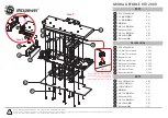
Page 17: ...7 Fig 1 1 Installation Flow Chart...

Page 18: ...h ActiveDAQ w Advantech GeniDAQ For more information on software please refer to Chapter 4 Software Programming Overview Users who intend to program directly at the registers of the multifunction card...

Page 19: ...le reducing cross talk and noise from other signal sources Furthermore its analog and digital lines are separately sheathed and shielded to neutralize EMI EMC problems Wiring Boards n ADAM 3968 The AD...

Page 20: ...in flat cable connectors for digital input and output w Reserved space on the board to meet future needs for signal conditioning circuits e g low pass filter voltage attenuator and current shunt w Ind...

Page 21: ...11 Installation and Configuration CHAPTER 2...

Page 22: ...rable to electrostatic discharge ESD ESD could easily damage the integrated circuits and certain components if preventive measures are not carefully paid attention to Before removing the card from the...

Page 23: ...system Also pay extra caution to the following aspects to ensure proper installation w Avoid physical contact with materials that could hold static electricity such as plastic vinyl and styrofoam w Wh...

Page 24: ...cluded on the companion CD ROM that is shipped with your DAS card package Please follow the steps below to install the driver software Step 1 Insert the companion CD ROM into your CD ROM drive Step 2...

Page 25: ...option Step 4 Select the specific device then just follow the installation instructions step by step to complete your device driver setup Fig 2 2 Different options for Driver Setup For further inform...

Page 26: ...card Step 1 Remove the cover of an unused cPCI slot on your computer Step 2 Hold the card vertically Be sure that the card is pointing in the correct direction The components of the card should be po...

Page 27: ...plane the Blue LED will be lit After Step 6 the system can configure the card automatically and the Blue LED turns off when the system finishes the device configuration To remove a card Step 1 Push th...

Page 28: ...should ignore the prompting messages just click the Cancel button and set up the driver according to the steps described in 2 2 Software Installation After the MIC 3716 card is installed you can verif...

Page 29: ...rd device from the Device Manager by selecting its device name and press the Remove button Then go through the driver installation process again After your card is properly installed on your system yo...

Page 30: ...s will be used when you call the APIs of Advantech Device Drivers Setting Up the Device Step 1 To install the I O device for your card you must first run the Advantech Device Manager program by access...

Page 31: ...21 Step 3 The Installed Devices box will list the device s found on your system such as the one in Fig 2 4 Fig 2 4 The Device Manager dialog box...

Page 32: ...can configure the source of D A reference voltage either as Internal or External and select the output voltage range When selecting voltage source as Internal you have two options for the output volt...

Page 33: ...2 6 Fig 2 6 The Device Name appears in the list of devices dialog box Note As you can see from the above figure the device name is 000 MIC 3716 BoardID 15 I O fd00H Each device name begins with a devi...

Page 34: ...test the device by clicking the Test Button on the Device Manager dialog box An Advantech Device Test dialog box will appear accordingly Fig 2 7 Fig 2 7 The Advantech Device Test dialog box In the Adv...

Page 35: ...thod For high speed data acquirement or output they have to use corresponding VC examples like ADINT ADDMA or ADBMDMA Testing the Analog Input Functions Click the Analog Input tab to bring it up to th...

Page 36: ...eground The Analog Output tab allows you to output quasi sine triangle or square waveforms generated by the software automatically or output single values manually You can also configure the waveform...

Page 37: ...tab to show the Digital Input test panel as seen below in figure 2 10 Through the color of the lamps you can discern whether the status of each digital input channel is either high or low Red high Gre...

Page 38: ...ut tab to bring up the Digital Output test panel such as the one seen on the next page By pressing the buttons on each tab you can set each digital output channel as high or low for the corresponding...

Page 39: ...counting after the pin CNT0_GATE is triggered If you select Pulse Out the clock source will be output to pin CNT0_OUT You can configure the Pulse Frequency with the scroll bar Fig 2 12 Counter tab on...

Page 40: ...30 This page is left blank for hard printing...

Page 41: ...31 Signal Connections CHAPTER 3...

Page 42: ...ides useful information about how to connect input and output signals to the MIC 3716 via the I O connector 3 2 I O Connector The I O connector on the MIC 3716 is a 68 pin connector that enables you t...

Page 43: ...d purpose An individual GND pin is available for AI AO and DIO to provide optimum signal quality Since all the signals on the DAS card need to refer to the same GND the manufacturer has tested and cho...

Page 44: ...34 Fig 3 1 I O connector pin assignments for the MIC 3716...

Page 45: ...connector as well as the 5VDC supply The three ground references AIGND AOGND and DGND are connected together CNT0_CLK DGND Input Counter 0 Clock Input The clock input of counter 0 can be either extern...

Page 46: ...ch channel and the measured voltage Vm is the voltage of the wire as referenced against the common ground A signal source without a local ground is also called a floating source It is fairly simple to...

Page 47: ...es is measured On the MIC 3716 when all channels are configured to differential input up to 8 analog channels are available If one side of the signal source is connected to a local ground the signal s...

Page 48: ...ltage Vcm between the signal source and the MIC 3716 ground shown as Vcm in Fig 3 3 Fig 3 3 Differential input channel connection ground reference signal source If a floating signal source is connecte...

Page 49: ...Differential input channel connection floating signal source This connection has the disadvantage of loading the source down with the series combination sum of the two resistors For ra and rb for exam...

Page 50: ...40...

Page 51: ...0 to 5 V 10 V D A output range You may also create a D A output range through external references AO0_REF and AO1_REF The external reference input range is 10 V For example connecting with an external...

Page 52: ...u can also use this signal as a synchronous signal for other applications External Trigger Source Connection In addition to pacer triggering the MIC 3716 also allows external triggering for A D conver...

Page 53: ...e of cable has its signal wires twisted together and shielded with a metal mesh The metal mesh should only be connected to one point at the signal source ground w Avoid running the signal cables throu...

Page 54: ...44 This page is left blank for hard printing...

Page 55: ...45 Software Programming Overview CHAPTER 4...

Page 56: ...iver to program your DAS cards Advanced users may also wish to choose register level programming although this is not recommended due to its laborious and time consuming nature 4 1 Programming Choices...

Page 57: ...M 4 2 DLL Driver Programming Roadmap This section will provide a roadmap to demonstrate how to build an application from scratch using the Advantech DLL driver with your favorite development tools suc...

Page 58: ...dily accessed through the Start button Start Programs Advantech Automation Device Manager Device Driver s Manual The example source codes should be found under the corresponding installation folder su...

Page 59: ...n Group For the usage and parameters of each function please refer to the Function Overview chapter in the DLL Drivers Manual Troubleshooting DLL Driver Error Driver functions will return a status cod...

Page 60: ...50 This page is left blank for hard printing...

Page 61: ...51 Calibration CHAPTER 5...

Page 62: ...orresponding subfolders in your destination directory The MIC 3716 has been calibrated at the factory for initial use However a calibration of the analog input and the analog output functions every si...

Page 63: ...indows environment You can access this program from the default location Program Files ADVANTECH ADSAPI Utilities MIC3716 5 2 VR Assignment There is one variable resistor VR1 on the MIC 3716 to adjust...

Page 64: ...libration procedures automatically however the user can calibrate the MIC 3716 manually Appendix E illustrates the standard calibration procedure for your reference If you want to calibrate the hardwa...

Page 65: ...talled the program to another directory you can find this program in the corresponding subfolders in your destination directory Step 2 Select MIC 3716 in the ADSDAQ dialog box Fig 5 2 Selecting the de...

Page 66: ...56 Step 3 After you start to calibrate the MIC 3716 please don t forget to adjust VR1 Fig 5 3 Warning message before start calibration...

Page 67: ...tion tab to show the A D channel auto calibration panel Fig 5 4 Press the start button to calibrate A D channels automatically Fig 5 4 Auto A D Calibration Dialog Box Step 5 The first A D calibration...

Page 68: ...58 Step 6 The second A D calibration procedure is enabled Fig 5 6 Fig 5 6 A D Calibration Procedure 2 Step 7 The third A D calibration procedure is enabled Fig 5 7 Fig 5 7 A D Calibration Procedure 3...

Page 69: ...the Auto D A Calibration tab to show the D A channel auto calibration panel Please finish the A D calibration procedure first before you start the D A calibration procedure There are two D A channels...

Page 70: ...60 Fig 5 9 Range Selection in D A Calibration Step 10 D A channel 0 calibration is enabled Fig 5 10 Fig 5 10 Calibrating D A Channel 0...

Page 71: ...61 Step 11 D A channel 1 calibration is enabled Fig 5 11 Fig 5 11 Calibrating D A Channel 1 Step 12 Auto calibration is finished Fig 5 12 Fig 5 12 D A Calibration is finished...

Page 72: ...ge value from a precision standard voltage reference Fig 5 13 Note n The input voltage value you selected from a precision standard voltage reference needs to correspond with the one that the MIC 3716...

Page 73: ...e in the Manual A D Calibration panel Step 2 Depending on the difference between reference voltage and the received data in MIC 3716 adjust the gain bipolar offset and unipolar offset registers Fig 5...

Page 74: ...ed in the Manual A D Calibration tab D A channel Manual Calibration Step 1 Click the Manual D A Calibration tab to show the D A channel manual calibration panel The two D A channels are individually c...

Page 75: ...For example choose channel 0 select the Range and select the wished output voltage code or value from the radio buttons Fig 5 15 and Fig 5 16 Fig 5 15 Fig 5 16 Selecting D A Range and Choosing Output...

Page 76: ...om D A channel and the value in the multi meter adjust the gain bipolar offset and unipolar offset registers Fig 5 17 Fig 5 17 Adjusting registers Step 4 Adjust registers until they fall between the o...

Page 77: ...67 Appendixes...

Page 78: ...z 1 5 M Hz 0 65 M Hz Common mode Voltage 11 V max operational Max Input Voltage 20V Input Protect 30 Vp p Input Impedance 100 MO 10 pF Off 100 MO 10 0pF On Trigger Mode Software On board Programmable...

Page 79: ...e 0 1O max Digital Input Output Input Channels 16 Low 0 4 V max Input Voltage High 2 4V min Low 0 4 V max 0 2mA Input Load High 2 7V min 20 A Output Channels 16 Low 0 4 V max 8 0 mA sink Output Voltag...

Page 80: ...l 5 V 850mA 12V 600mA Power Consumption Max 5 V 1 A 12V 700mA Operation 0 60 C 32 158 refer to IEC 65 2 1 2 Temperature Storage 20 85 C 4 158 Operation 5 85 RH non condensing refer to IEC 68 1 2 3 Rel...

Page 81: ...71 Appendix B Block Diagrams...

Page 82: ...72 This page is left blank for hard printing...

Page 83: ...C 3716 at the register level is to understand the function of the card s registers The information in the following sections is provided only for users who would like to do their own low level program...

Page 84: ...7 6 5 4 3 2 1 0 A D Data 1 AD15 AD14 AD13 AD12 AD11 AD10 AD9 AD8 0 AD7 AD6 AD5 AD4 AD3 AD2 AD1 AD0 N A 3 2 N A 5 4 A D Status Register 7 CAL IRQ F F F H F E 6 AD16 12 CNT0 ONE FH IRQEN GATE EXT PACER...

Page 85: ...3 2 1 0 Digital Input 17 DI15 DI14 DI13 DI12 DI11 DI10 DI9 DI8 16 DI7 DI6 DI5 DI4 DI3 DI2 DI1 DI0 N A 19 18 Board ID 21 20 BD3 BD2 BD1 BD0 N A 23 22 Counter 0 25 24 D7 D6 D5 D4 D3 D2 D1 D0 Counter 1 2...

Page 86: ...Control Register 7 CAL 6 AD16 12 CNT0 ONE FH IRQEN GATE EXT0 PACER SW Clear Interrupt and FIFO 9 Clear FIFO 8 Clear interrupt D A Output Channel 0 11 DA15 DA14 DA13 DA12 DA11 DA10 DA9 DA8 10 DA7 DA6 D...

Page 87: ...DO12 DO11 DO10 DOI9 DO8 16 DO7 DO6 DO5 DO4 DO3 DO2 DO1 DO0 Calibration Command and Data 19 CM3 CM2 CM1 CM0 18 D7 D6 D5 D4 D3 D2 D1 D0 N A 21 20 N A 23 22 Counter 0 25 24 D7 D6 D5 D4 D3 D2 D1 D0 Count...

Page 88: ...onversion are stored in BASE 1 bit 7 to bit 0 and BASE 0 bit 7 to bit 0 Table C 2 MIC 3716 Register for A D data Read A D Data Bit 7 6 5 4 3 2 1 0 BASE 1 AD15 AD14 AD13 AD12 AD11 AD10 AD9 AD8 BASE 0 A...

Page 89: ...rsion by software the card s on board pacer or an external pulse BASE 6 Bit 2 to bit 0 select the trigger source see Section C 7 Control Register BASE 6 If you select software triggering a write to th...

Page 90: ...in BASE 4 the start channel and BASE 5 the stop channel refer to Section C 6 w Write the gain code to BASE 2 bit 0 to bit 2 Table C 3 Register for A D channel range setting Write A D Channel Range Se...

Page 91: ...1 0 5 10 to 10 0 1 0 0 N A 0 1 0 1 N A 0 1 1 0 N A 0 1 1 1 1 0 to 10 1 0 0 0 2 0 to 5 1 0 0 1 4 0 to 2 5 1 0 1 0 8 0 to 1 25 1 0 1 1 N A 1 1 0 0 N A 1 1 0 1 N A 1 1 1 0 N A 1 1 1 1 Example To set cha...

Page 92: ...expected errors In fact BASE 4 bit 3 to bit 0 STA3 STA0 act as a pointer to channel n s address in the SRAM when you program the A D channel setting refer to Section C 5 Caution We recommend you to se...

Page 93: ...xamples show the scan sequences of the Multiplexer Example 1 If the start scan input channel is AI3 and the stop scan input channel is AI7 then the scan sequence is AI3 AI4 AI5 AI6 AI7 AI3 AI4 AI5 AI6...

Page 94: ...ll be a little bit different If we set two AI channels as differential channels it will be considered as one channel in the data array Since the resulted data array of the multi channel scan function...

Page 95: ...85 Warning Only even channels can be set as differential An odd channel will become unavailable if its preceding channel is set as differential...

Page 96: ...us Register Bit 7 6 5 4 3 2 1 0 BASE 7 CAL BASE 6 AD16 12 CNT0 ONE FH IRQEN GATE EXT PACER SW SW Software trigger enable bit 1 enable 0 disable PACER Pacer trigger enable bit 1 enable 0 disable EXT Ex...

Page 97: ...unter 0 comes from the external clock maximum up to 10 MH AD16 12 Analog Input resolution 0 16 bit 1 12 bit And those two registers BASE 0 BASE 1 Table C 7 Table C 7 MIC 3716 Register for channel numb...

Page 98: ...SB CAL Analog I O calibration bit 0 Normal mode All analog input and outputs channels are connected to the 68 pin SCSI II connector respectively 1 A D and D A calibration mode The wiring becomes that...

Page 99: ...The content of the status register of BASE 6 is the same as that of the control register F E FIFO Empty flag This bit indicates whether the FIFO is empty 1 means that the FIFO is empty F H FIFO Half f...

Page 100: ...10 and BASE 11 The MIC 3716 provides an innovative design as gate control for the Analog Output function It works as a general Analog Output function when you disable the flag bit 3 DA0_LDEN of BASE 1...

Page 101: ...accept data for the D A Channel 0 output Table C 11 Register for D A channel 0 data Write D A Output Channel 0 Bit 7 6 5 4 3 2 1 0 BASE 11 DA15 DA14 DA13 DA12 DA11 DA10 DA9 DA8 BASE 10 DA7 DA6 DA5 DA4...

Page 102: ...Output function when you disable the flag bit 11 DA1_LDEN of BASE 14 That means the data will be output immediately However when you enable the flag you need to read these two registers BASE 12 and B...

Page 103: ...accept data for the D A channel 1 output Table C 13 Register for D A channel 1 data Write D A Output Channel 1 Bit 7 6 5 4 3 2 1 0 BASE 13 DA15 DA14 DA13 DA12 DA11 DA10 DA9 DA8 BASE 12 DA7 DA6 DA5 DA4...

Page 104: ...DA1_LDEN DA1_I E DA0_B U DA1_5 10 BASE 14 DA0_LDEN DA0 I E DA0_B U DA0_5 10 DAn_5 10 The internal reference voltage for the D A output channel n 0 5 V 1 10 V DAn_B U for D A output channel n 0 Bipolar...

Page 105: ...7 6 5 4 3 2 1 0 BASE 17 DI15 DI14 DI13 DI12 DI11 DI10 DI9 DI8 BASE 16 DI7 DI6 DI5 DI4 DI3 DI2 DI1 DI0 Table C 16 Register for digital output Write Digital Output Bit 7 6 5 4 3 2 1 0 BASE 17 DO15 DO14...

Page 106: ...D A Table C 17 Calibration Command and Data Register Write Calibration Command and Data Bit 7 6 5 4 3 2 1 0 BASE 19 CM3 CM2 CM1 CM0 BASE 18 D7 D6 D5 D4 D3 D2 D1 D0 D7 to D0 Calibration data D0 LSB of...

Page 107: ...adjust 0 0 0 1 PGA offset adjust 0 0 1 0 A D gain adjust 0 0 1 1 D A 0 gain 1 adjust 10 V 0 1 0 0 D A 0 gain 2 adjust 5 V 0 1 0 1 D A 0 bipolar offset adjust 0 1 1 0 D A 0 unipolar offset adjust 0 1...

Page 108: ...ister for Board ID Read Board ID Bit 7 6 5 4 3 2 1 0 BASE 20 BD3 BD2 BD1 BD0 C 18 Programmable Timer Counter Registers BASE 24 BASE 26 BASE 28 and BASE 30 The four registers of BASE 24 BASE 26 BASE 28...

Page 109: ...put clock frequency of 10 MHz The MIC 3716 provides 10 MHz input frequencies to the counter chip from an on board crystal oscillator Counter 0 On the MIC 3716 counter 0 can be a 16 bit timer or an eve...

Page 110: ...32 bit timer for the pacer trigger A low to high edge of counter 2 output PACER_OUT will trigger an A D conversion At the same time you can use this signal as a synchronous signal for other applicati...

Page 111: ...Dec Counter 1 read write BASE 28 Dec Counter 2 read write BASE 30 Dec Counter control word Since the 82C54 counter uses a 16 bit structure each section of read write data is split into a least signif...

Page 112: ...RW1 RW0 Counter latch 0 0 Read write LSB 0 1 Read write MSB 1 0 Read write LSB first 1 1 then MSB M2 M1 M0 Select operating mode M2 M1 M0 Mode Description 0 0 0 0 Stop on terminal count 0 0 1 1 Progra...

Page 113: ...he counter control register is in read back command mode The control register data format then becomes BASE 30 Dec 82C54 control read back mode Bit D7 D6 D5 D4 D3 D2 D1 D0 Value 1 1 CNT STA C2 C1 C0 X...

Page 114: ...becomes BASE 24 26 28 Dec Status read back mode Bit D7 D6 D5 D4 D3 D2 D1 D0 Value OUT NC RW1 RW0 M2 M1 M0 BCD OUT Current state of counter output NC Null count is 1 when the last count written to the...

Page 115: ...cond byte starts the new count MODE 1 Programmable One shot Pulse The output is initially high The output will go low on the count following the rising edge of the gate input It will then go high on t...

Page 116: ...mbers and will go low for the other half of the count This is accomplished by decreasing the counter by two on the falling edge of each clock pulse When the counter reaches the terminal count the stat...

Page 117: ...low for one input clock period then go high again If you reload the count register during counting the new count will be loaded on the next CLK pulse The count will be inhibited while the GATE input i...

Page 118: ...the 82C54 convention is acceptable There are three types of counter operations Read load LSB read load MSB and read load LSB followed by MSB It is important that you make your read write operations in...

Page 119: ...without disturbing the count in progress You do this by latching the count value for the specific counter and then read the value The 82C54 supports the counter latch operation in two ways The first...

Page 120: ...110 This page is left blank for hard printing...

Page 121: ...5 0000 V Next to write 0x0080 0x0180 0x0280 and 0x0380 sequentially to the Calibration Command and Data register BASE 18 set MIC 3716 to AI software trigger and calibration mode 2 Adjust the PGA offs...

Page 122: ...p again until the average data is close to 32767 5 6 Adjust UNIPOLAR offset voltage First write any value to BASE 9 to clear FIFO Then set A D channel to channel 0 and set the range as 0 V to 10 V 7 W...

Page 123: ...tep Otherwise you must change the value and repeat the whole procedure in this step again until the average data is close to 65534 6 10 Repeat steps 2 to 9 several times Table E 1 A D binary code tabl...

Page 124: ...h the D A calibration procedure automatically In order to get the maximum possible accuracy of the D A channels you need to calibrate the A D channels first Although the procedure is not necessary the...

Page 125: ...O Then set the A D range as 5 V to 5 V and set the D A range as 0 V to 5 V Next write 0xFFFF to the corresponding D A registers BASE 10 and BASE 12 5 Write the value from 0x0500 to 0x05FF sequentially...

Page 126: ...ation First write any value to BASE 9 to clear FIFO Then set the A D range as 5 V to 5 V and set the D A range as 0 V to 5 V Next write 0x8000 to the corresponding D A registers BASE 10 and BASE 12 9...

Page 127: ...nipolar 0000h 0 FS 0 7FFFh 32767 1 LSB 0 5 FS 1 LSB 8000h 32768 0 0 5 FS FFFFh 65535 FS 1 LSB FS 1 LSB Note n 1 LSB FS 65535 for Unipolar For example 1LSB 10 65535 while the range is 0 V to10 V n 1 LS...

Reviews: