Advanced Radio I Charger, Instructions Manual
Introducing our Advanced Radio I Charger, a state-of-the-art device delivering efficient charging capabilities for your radio. To ensure hassle-free usage, we provide a comprehensive Instructions Manual, available for free download from our website. Simply access manualshive.com to get your hands on this invaluable resource, enabling seamless operation and optimal performance.
Share
Download


Reviews:
No comments
Related manuals for I Charger

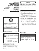
LJ-SK56A
Brand: Panasonic Pages: 132

EY0225
Brand: Panasonic Pages: 52

EY-0110
Brand: Panasonic Pages: 4
Toughbook CF-29CTKGZKM
Brand: Panasonic Pages: 4

Attune WX-Z3040
Brand: Panasonic Pages: 20

SPAS-2400/4
Brand: VOLTCRAFT Pages: 8

PB-80C24
Brand: JAR Systems Pages: 2

iON Wireless Duo
Brand: iOttie Pages: 11

75P-T6-Multi-Charger
Brand: Thunder Pages: 37

Pump In Style Battery Pack
Brand: Medela Pages: 2

AA-C4H
Brand: WATSON Pages: 12

BC 2420
Brand: Calix Pages: 4

eVault Max 18.5
Brand: Fortress Power Pages: 2

REVOLT A3
Brand: Prestigio Pages: 20

PLUS POWER 60
Brand: RC-Plus Pages: 24

5010000320
Brand: Coleman Pages: 2

CBC-9140
Brand: Manson Engineering Industrial Pages: 15

5-Hour AA & AAA Ni-Cd/Ni-MH Battery Charger
Brand: Radio Shack Pages: 4


