background image

Quick Start

Overview

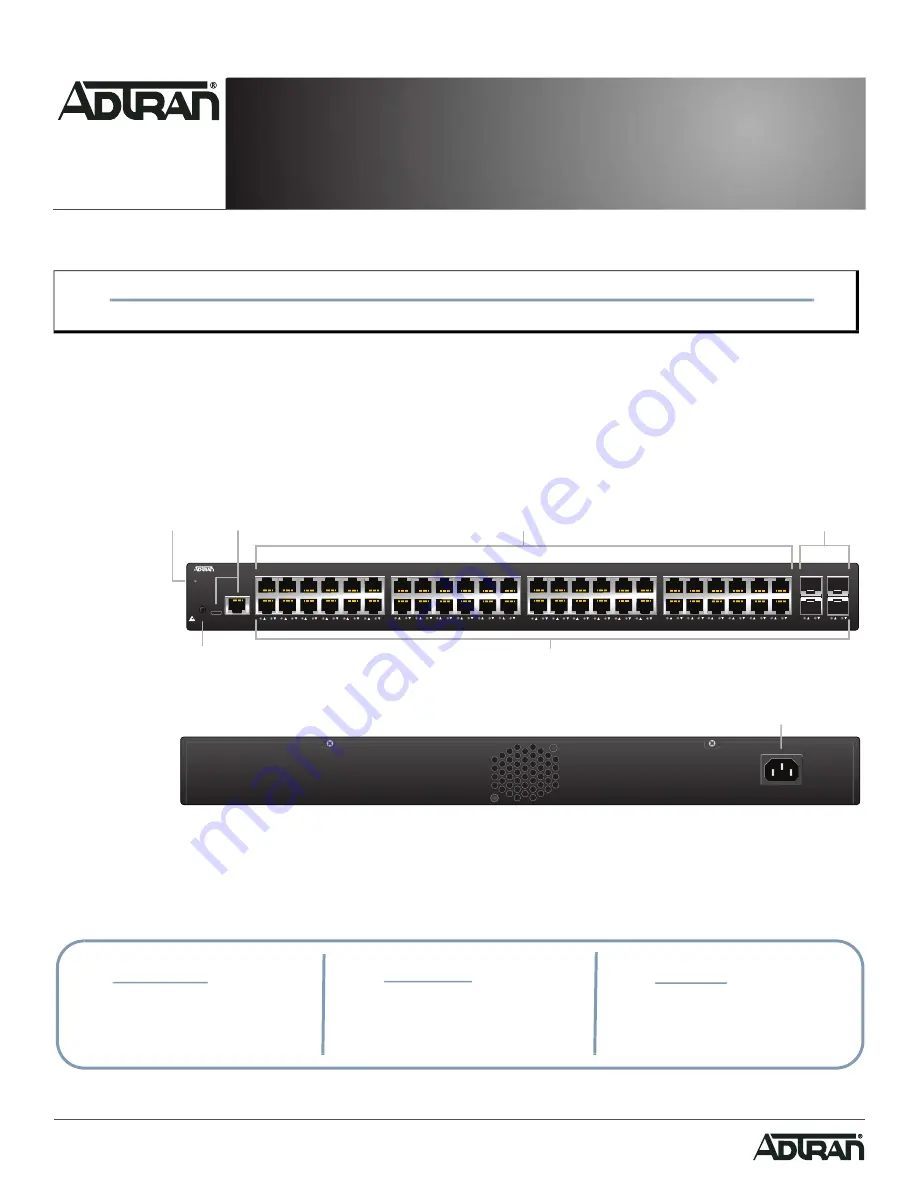
This quick start describes how to install, configure, and troubleshoot the NetVanta 1560-48, 48-port managed GbE switch. Figures 1 and 2 show the Front 

and Rear Panel layouts of the switch. 

“Installing the Switch” 

on page 2

“Connecting to the Switch” 

on page 5

“Understanding the Status LEDs” 

on page 6

“Resetting the Switch” 

on page 7

“Troubleshooting the Switch” 

on page 7

“Product Specifications” 

on page 7

Figure 1. Front Panel Layout

Figure 2. Rear Panel Layout

WARNING!

f

Read all warnings, cautions, notes and installation instructions before installing or servicing this equipment.

NetVanta 1560-48

SYSTEM

CONSOLE

USB

RESET

1

2

3

4

5

6

7

8

9

10

11

12

13

14

15

16

17

18

19

20

21

22

23

24

51

52

25

26

27

28

29

30

31

32

33

34

35

36

37

38

39

40

41

42

43

44

45

46

47

48

49

50

RESET

Button

Port Status

LEDs

SYS

LED

CONSOLE

Port

10/100/1000/2500

RJ-45

1G/2.5G/10G

SFP+ Ports

AC Line: 100-240V 50-60Hz

AC Line: 100-240V 50-60Hz

Power Connection

f


WARNING!

f


CAUTION!

g

     NOTE

WARNING indicates a hazard which, if 

not avoided, could result in death, injury 

or serious property damage.

CAUTION indicates a hazard which, if not 

avoided, could result in service interruption, 

damage to the equipment, or minor property 

damage.

NOTES inform the user of additional, but 

important, information or features.

NetVanta 1560-48

48-port Managed GbE Switch

April 2022

617101568F1-13A

P/N: 17101568F1

Summary of Contents for NetVanta 1560-48

Page 1: ...ipment NetVanta 1560 48 SYSTEM CONSOLE USB RESET 1 2 3 4 5 6 7 8 9 10 11 12 13 14 15 16 17 18 19 20 21 22 23 24 51 52 25 26 27 28 29 30 31 32 33 34 35 36 37 38 39 40 41 42 43 44 45 46 47 48 49 50 RESET Button Port Status LEDs SYS LED CONSOLE Port 10 100 1000 2500 RJ 45 1G 2 5G 10G SFP Ports AC Line 100 240V 50 60Hz AC Line 100 240V 50 60Hz Power Connection f WARNING f CAUTION g NOTE WARNING indica...

Page 2: ...ewdriver to secure the brackets Figure 3 Attaching Brackets to the Switch 2 Position the chassis in the stationary equipment rack Allow 1 inch of clearance between units NOTE g Refer to the national state and local electrical codes for the requirements for power grounding wiring and installation methods CAUTION f The NetVanta 1560 48 is intended for indoor use only Ethernet PoE cables and attached...

Page 3: ... Supplying Power to the Switch To connect the AC power cord to the switch complete the following steps 1 Connect the AC power cord to the AC power receptacle on the rear panel of the switch 2 Connect the other end of the AC power cord to a properly grounded AC power outlet The AC branch circuit socket outlet must be installed near the equipment and must be easily accessible NOTE g Rack mount brack...

Page 4: ...nal state and local electrical code requirements as applicable The AC branch circuit overcurrent protection must be a fuse or circuit breaker rated 125 VAC 20 Amps maximum or 250 VAC 16 Amps maximum A readily accessible disconnect device that is suitably approved and rated must be incorporated in the field wiring CAUTION f It is recommended that an external AC Surge Protection Device be installed ...

Page 5: ...e g 255 255 255 0 g Select OK to change the PC s IP address 3 Power up the switch to be initially configured and wait until it has finished its start up processes 4 Connect the PC to any port on the switch using a standard Ethernet cable and check the port LED on the switch to make sure the link status of the PC is OK 5 Run your web browser on the PC enter either the DHCP assigned or factory defau...

Page 6: ...m has been triggered for troubleshooting Port Status LEDs The Port Status LEDs indicate the current status of each port NOTE g The factory default username of the switch is admin The factory default password is password NOTE g There are many terminal emulation applications available on the web PuTTY SecureCRT and HyperTerminal are a few examples LED Color State Description SYSTEM Off The switch is...

Page 7: ...store to Factory Defaults 7 12 seconds Flashing Green All LEDs are ON Symptoms Possible Causes Suggested Solutions System LED is OFF The switch is not receiving power 1 Check if correct power cord is connected firmly to the switch and to the AC outlet socket 2 Cycle the power on the switch by unplugging and plugging the power cord back into the switch 3 If the LED is still off try plugging the pow...

Page 8: ...ng or maintaining always place devices on an approved antistatic mat that is electrically grounded Warranty ADTRAN will replace or repair this product within the warranty period if it does not meet its published specifications or fails while in service Warranty information can be found online at www adtran com warranty Trademarks Brand names and product names included in this document are trademar...

Reviews: