ADEMCO 7720V2, Installation Instructions Manual
The ADEMCO 7720V2 is a reliable security system designed for residential and commercial use. Ensure a seamless installation with the comprehensive Installation Instructions Manual available for free download from our website. Get all the essential details and step-by-step guidance to set up your security system effortlessly.
Share
Download


Reviews:
No comments
Related manuals for 7720V2

Sure Cross MultiHop
Brand: Banner Pages: 6

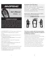
UV-82
Brand: Baofeng Pages: 74

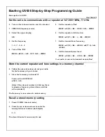
UV-5R Series
Brand: Baofeng Pages: 74
BF-88A
Brand: Baofeng Pages: 3
UV-B5
Brand: Baofeng Pages: 2

BELT-PAK 5 Series
Brand: EARMARK Pages: 2

VT-3501
Brand: Vitek Pages: 6

JCR-275
Brand: Jensen Pages: 12

KK-C310
Brand: kchibo Pages: 3
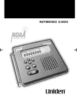
WX500
Brand: Uniden Pages: 32

ATT-400/AODC
Brand: RJE Pages: 13

SY 1035
Brand: Sytech Pages: 7

BRCM1017
Brand: Intermec Pages: 8

SN-SMWR02A
Brand: UNELL Pages: 9

CK5030
Brand: Emerson Pages: 12

CK5888
Brand: Emerson Pages: 2

CK5038
Brand: Emerson Pages: 19

CK5250
Brand: Emerson Pages: 17


