Addi-Data ADDICOM PA 7400 Series, Technical Description
The Addi-Data ADDICOM PA 7400 Series is a cutting-edge, high-performance data acquisition system. This technical description manual provides comprehensive insights into the features, specifications and installation process for the product. Download this manual for free from our website and unleash the full potential of your ADDICOM PA 7400 Series.
Share
Download


Reviews:
No comments
Related manuals for ADDICOM PA 7400 Series

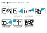
402031
Brand: cable matters Pages: 2

201049
Brand: cable matters Pages: 12

102021
Brand: cable matters Pages: 2

DC60Xu
Brand: Pace Pages: 14
PiSystem
Brand: KAT VR Pages: 2

CN3E Series
Brand: Intermec Pages: 2

Baby Trend Expedition U-shaped Support Bar (facing up)Baby Trend Flex LocBaby Trend GabriellaBaby Trend Stride SportBaby
Brand: Baby Jogger Pages: 5

00133753
Brand: Hama Pages: 74

LC 2130
Brand: Leader Pages: 12

PSSE27
Brand: Velleman Pages: 4

AUSB
Brand: Fein Pages: 145

WRT54GP2 - Wireless-G Broadband Router
Brand: Linksys Pages: 5

28787
Brand: BAZOO Pages: 2

62104
Brand: Goobay Pages: 5

DN-30210
Brand: Digitus Pages: 30

7707-K125
Brand: NCR Pages: 16

7360-K502
Brand: NCR Pages: 38

DX-CRDRD
Brand: Dynex Pages: 20


