


Field Service Documentation
1
Snap Server 4200/4500
Copyright © 2007, Adaptec, Inc. All rights reserved. Information in this document is subject to change without notice and does not represent
a commitment on the part of Adaptec or any of its subsidiaries.
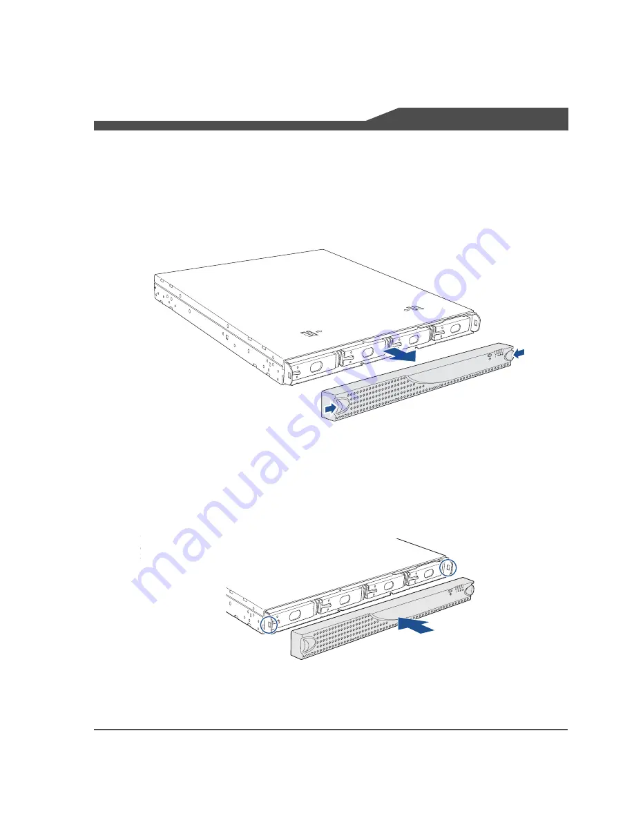
Replacing the Front Bezel
Note
These instructions apply to multiple models; illustrations may vary slightly.
Removing the Front Bezel
1
Press the latches, one on each side of the front bezel.
2
Still holding the latches in the release position, pull the bezel away from the
chassis.
Replacing the Front Bezel
1
Position the new bezel so the tabs line up to slide under the top edge of the cover.
2
Press firmly to attach the bezel. A muted click indicates the latches are locked.


