background image

Please Read This Manual

Congratulations on your purchase of an 

ActronAir air conditioning system. This unit 

has been designed and manufactured with 

the highest quality standard in mind.

Please read this manual thoroughly and keep 

it near the unit for future reference.
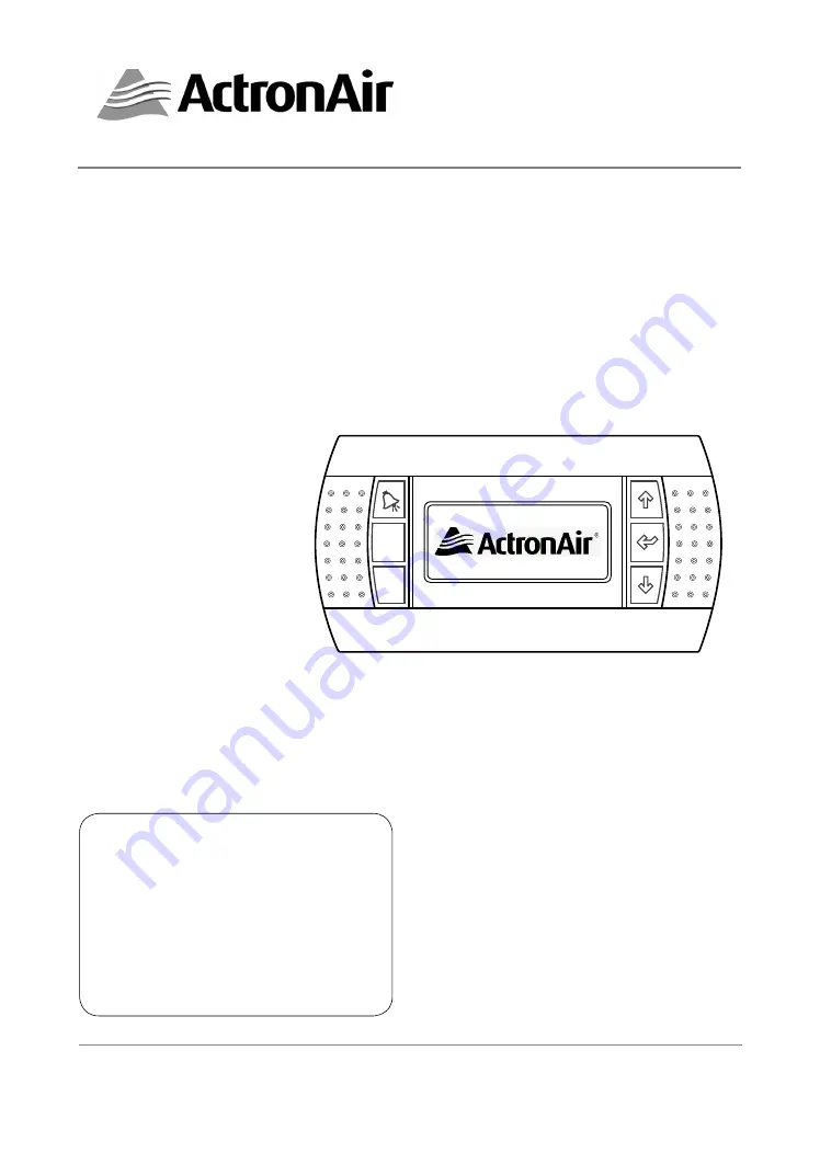
Esc

Prg

®

HERCULES AIR CONDITIONING SYSTEM

CONTROL INTERFACE
Operating Instructions

Copyright © 2016 Actron Engineering Pty. Ltd. All rights reserved. 

This manual is a controlled document which contains confidential and proprietary information. 

Distribution, modification, copying and/or reproduction are prohibited without written consent from ActronAir.

Model Number 

CP10

APPLICABLE TO

HERCULES MODELS 

(PKV1400  PKV1700  PKV2000)

Summary of Contents for CP10

Page 1: ...unit for future reference Esc Prg HERCULES AIR CONDITIONING SYSTEM CONTROL INTERFACE Operating Instructions Copyright 2016 Actron Engineering Pty Ltd All rights reserved This manual is a controlled document which contains confidential and proprietary information Distribution modification copying and or reproduction are prohibited without written consent from ActronAir Model Number CP10 APPLICABLE ...

Page 2: ...11 Sub Menu Level Descriptions 12 Operation Mode 13 Turn Unit ON OFF via Control Interface 14 Setting Room Temperature 15 Setting Supply Air Pressure Setpoint 16 Setting Filter Pressure Alarm Setpoint 17 Setting the Clock 18 7 Day Programming 20 After Hour Timer 22 Day Light Saving Time Enable 23 Day Light Saving Time Disable 25 Status Read Only Menu 26 Data Logger Read Only Menu 27 Dual Control O...

Page 3: ...sults in relation to the specific design and system installation ActronAir based on specific agreements may be consulted for the positive commissioning installation and application of the unit however in no case does ActronAir accept liability for the correct operation of the final equipment system Your ActronAir air conditioning unit is one of the most advanced innovative products in the market I...

Page 4: ...ing ways to improve the design of its products therefore specifications are subject to change without prior notice Please check with your Customer Care Department on toll free number 1800 119 229 Storage Operating Conditions Storage conditions 20 to 70 o C 90 RH non condensing Operating conditions 10 to 60 o C 90 RH non condensing Waste Electrical Electronic Equipment Disposal Guidelines 1 Do not ...

Page 5: ...ctrical authority regulations and all wiring connections to be as per electrical diagram provided 7 WH S rules and regulations must be observed and will take precedence during installation process 8 Only use this wall controller with an ActronAir air conditioner as described in this operating manual ACCESS PANELS AND GUARDS NEVER remove any access panels or guards as this could cause injury from e...

Page 6: ...increase setting parameter Enter Button To lock the selected menu or to enter set parameters Scroll Down Decrement Button To scroll down from existing menu or to decrease setting parameter 4 5 6 7 SYSTEM DEFAULT SCREEN Return Temp 23 7 o C 16 4 o C Supply Temp Comp Rev Vlv Defrost 10 20 Unit Unit ONbyKEY Current Time Unit ON OFF Indicator via Control Interface Actual Return Air Temperature Reversi...

Page 7: ...versing Valves are Off as indicated by clear triangles Esc Prg Return Temp 23 7 o C 16 4 o C Supply Temp Comp Rev Vlv 10 20 Unit Unit ONbyKEY Esc Prg ActronAir logo will then be displayed for the next 5 10 seconds Compressor 1 Reversing Valve 1 are On System in Heat Mode first triangles are darkened Return Temp 23 7 o C 16 4 o C Supply Temp Comp Rev Vlv Defrost 10 20 Unit Unit ONbyKEY Esc Prg Esc ...

Page 8: ...7 o C 16 4 o C Supply Temp Comp Rev Vlv Defrost 10 28 Unit Unit ONbyKEY Return Temp 23 7 o C 16 4 o C Supply Temp Comp Rev Vlv 10 23 Unit Unit ONbyKEY Return Temp 23 7 o C 16 4 o C Supply Temp Comp Rev Vlv 10 28 Unit Unit ONbyKEY Return Temp 23 7 o C 16 4 o C Supply Temp Comp Rev Vlv 10 23 Unit Unit ONbyKEY Return Temp 23 7 o C 16 4 o C Supply Temp Comp Rev Vlv 10 29 Unit Unit ONbyKEY Return Temp ...

Page 9: ...arms Speed Status Request Feedback Dissip temp DC volyage Motor data Speed Voltage Current VSD 2 Status Run Alarms Speed Status Request Feedback Dissip temp DC volyage Motor data Speed Voltage Current Outdoor Fan 3 Status Actual Max Speed DC Voltage DC Current Output Power Elec Temperature Outdoor Fan 2 Status Actual Max Speed DC Voltage DC Current Output Power Elec Temperature Outdoor Fan 4 Statu...

Page 10: ...only Menu screen to view the unit running conditions such as Supply Return Air temperature Airflow Outside temperature Condensing temperatures LP HP Supply Air pressure Discharge Temperatures Fans Speed Variable Speed Drive operating conditions etc F Alarm History Sub Menu Level Read only Menu screen that indicates the alarm history Sub Menu Level Indicator Level 1 of 8 levels Sub Menu Title Descr...

Page 11: ... to scroll into COOL ONLY mode Display will show COOL ONLY mode with the cursor still blinking 6 Press Button to lock in COOL ONLY mode the cursor will disappear indicating that the operation is now in COOL ONLY mode Note To Select HEAT ONLY FAN ONLY or AUTO CHANGE OVER Mode follow steps 4 to 6 above TO RETURN TO THE MAIN MENU 7 Keep pressing Esc Escape Return Button until you get to the Main Menu...

Page 12: ...o Turn On the unit The cursor will disappear and the unit will Turn On TO TURN OFF THE UNIT 6 Repeat Steps 1 2 then press Button cursor will appear and blinking near ON 7 Press or Button to select switch OFF position Display will show the ON OFF page with switch symbol pointing towards OFF and the cursor still blinking 8 Press Button to Turn Off the unit The cursor will disappear and the unit will...

Page 13: ...decremental value of 0 10 C 6 Press Button to lock in your desired room set point temperature The cursor will disappear and the new room setpoint temperature will be displayed TO RETURN TO THE MAIN MENU 7 Keep pressing Esc Escape Return Button until you get to the Main Menu screen Otherwise press Prg Button Display Progression A On Off Unit B Setpoint Main Menu A C Mode of Operation A On Off Unit ...

Page 14: ... hour set screen will appear Press Button to scroll down into c Thermoregulation 7 Press Button to lock in c Thermoregulation sub menu Note Thermoregulat Gfc1 screen will appear 8 Press Button to get into Thermoregulat Gfc4 screen 9 Press Button to lock in Thermoregulat Gfc4 sub menu and the cursor will appear next to Supply Air Volume Setpoint 10 Press or Button to change Supply Air Volume Setpoi...

Page 15: ...ent c Thermoregulation Service Menu Gfa c Thermoregulation b Probe adjustment a Working hour set Service Menu Gfa Step 5A Step 5B Step 6 Return Temperature Setpoint 16 0O C Dead band 0 5O C Prop band 4 0O C Thermoregulat Gfc1 Filter Pressure Alarm Setpoint 300Pa Supply Air Volume Setpoint 8850L s Apply changes now No Thermoregulat Gfc4 Filter Pressure Alarm Setpoint 300Pa Supply Air Volume Setpoin...

Page 16: ...rwise press Prg Button Display Progression A On Off Unit B Setpoint Main Menu A C Mode of Operation A On Off Unit B Setpoint Main Menu B C Mode of Operation Room Setpoint 22 0 o C Room Setpoint 60 0 rH Setpoint B1 Filter Pressure Alarm Setpoint 300Pa Supply Pressure Setpoint 650Pa Apply changes now No Setpoint B2 Step 1 Filter Pressure Alarm Setpoint 300Pa Supply Pressure Setpoint 650Pa Apply chan...

Page 17: ...sday 19 04 2016 19th April 2016 9 Press or Button to change the year Note Date changes as follows Tuesday 19 04 16 19th March 2015 Tuesday 19 04 16 19th May 2017 SETTING THE CLOCK Display Progression A On Off Unit B Setpoint Main Menu A C Mode of Operation C Mode of Operation B Setpoint Main Menu D D Clock Scheduler Hour 08 37 Enable Night mode No Enable Scheduler No Date 18 04 16 Day Monday Clock...

Page 18: ...day Clock D1 C Mode of Operation B Setpoint Main Menu D D Clock Scheduler Step 13 08 37 Step 13 08 39 Step 14 Step 15 A On Off Unit B Setpoint Main Menu A C Mode of Operation Step 15 10 Press Button to lock in the Year Date and the cursor will move next to the hour indicator 11 Press or Button to change the hour Note Hour can be changed with an incremental value of 1 hour 12 Press Button to lock i...

Page 19: ...chedule D3 Monday Event 1 17 00 to 00 00 Event 2 00 00 to 00 00 Tuesday Event 1 00 00 to 00 00 Event 2 00 00 to 00 00 Clock Schedule D3 Monday Event 1 17 01 to 00 00 Event 2 00 00 to 00 00 Tuesday Event 1 00 00 to 00 00 Event 2 00 00 to 00 00 Clock Schedule D3 Monday Event 1 17 59 to 00 00 Event 2 00 00 to 00 00 Tuesday Event 1 00 00 to 00 00 Event 2 00 00 to 00 00 Clock Schedule D3 Step 7 Step 8 ...

Page 20: ...t B Setpoint Main Menu A C Mode of Operation Step 12 Step 13 10 Press to lock in Monday Event 1 start time the cursor will now move to Monday Event 1 end time Example Monday Event 1 starting time is set at 5 00 PM i e 17 00 11 Repeat steps 7 10 to set up Monday Event 1 end time and the cursor will next move to Monday Event 2 start time indicator Example Monday Event 1 ending time is set at 10 30 P...

Page 21: ...remental value of 1L s 7 Press Button to lock in the desired duration of the After Hours operation TO RETURN TO THE MAIN MENU 8 Keep pressing Esc Escape Return Button until you get to the Main Menu screen Otherwise press Prg Button Display Progression A On Off Unit B Setpoint Main Menu A C Mode of Operation C Mode of Operation B Setpoint Main Menu D D Clock Scheduler Hour 09 38 Enable Night mode N...

Page 22: ...al Day 1 can be programmed from Day 1 to 31 of the month 7 Press Button to lock in the desired Day The cursor move next to the Month prompt 8 Press or Button to select the desired Month for Special Day 1 9 Press Button to lock in the desired Month The cursor move next to the Event 1 prompt 10 Follow steps 7 12 of the 7 Day Programming procedure to program Event 1 and Event 2 Notes The scheduled pr...

Page 23: ...00 00 Event 2 00 00 to 00 00 Clock Schedule D8 Special Day 1 Day 1 Month Event 1 00 00 to 00 00 Event 2 00 00 to 00 00 Clock Schedule D8 Special Day 1 Day 3 Month Event 1 00 00 to 00 00 Event 2 00 00 to 00 00 Clock Schedule D8 Step 5 Step 6 Step 7 Special Day 1 Day 3 Month Dec Event 1 00 00 to 00 00 Event 2 00 00 to 00 00 Clock Schedule D8 Special Day 1 Day 3 Month Jan Event 1 00 00 to 00 00 Event...

Page 24: ...o to D Clock Scheduler sub menu following the procedures from Setting the Clock section 2 Press the Button to get into Clock D2 Daylight Saving Time sub menu 3 Press Button to lock in Daylight Saving Time sub menu and the cursor will appear on ENABLE indicator 4 Press Button again to enable Daylight Saving Time mode and the cursor will move to the Transition time segment 5 Press or Button to selec...

Page 25: ... DST ENABLE Transition time 60 min Start FIRST SUNDAY in OCTOBER at 2 00 End FIRST SUNDAY in APRIL at 3 00 C Mode of Operation B Setpoint Main Menu D D Clock Scheduler Step 13 Step 14 Step 15 A On Off Unit B Setpoint Main Menu A C Mode of Operation Step 15 11 Press or Button to select the hour on the Sunday for the transition into daylight saving time Note The time clock is in 24 00 format i e 2 0...

Page 26: ...tes 1 Use the or Button to toggle on all of the D Clock sub menu functions 2 The programmed Day Light Saving Time parameters will be retained for next time Day Light Saving Time is enabled 1 From the main menu scroll down into D Clock Scheduler sub menu following the procedures from Setting the Clock section 2 Press Button to scroll down into Daylight Saving Time sub menu 3 Press Button to lock in...

Page 27: ...f DRM3 70 cap off DRM2 45 cap off Remote On Off off Status DIN E7 C Mode of Operation Main Menu E D Clock E Status Step 5 Step 6 Step 7 A On Off Unit B Setpoint Main Menu A C Mode of Operation Step 7 STATUS Read Only Menu Esc Prg Return Temp 23 8 o C Outside Temp 27 6 o C Supply Temp 22 0 o C Input Output_AIN 01 1 Press Prg Button to get into the Main Menu Display will show Main Menu and highlight...

Page 28: ...on A On Off Unit B Setpoint Main Menu A C Mode of Operation F Alarm History Main Menu F D Clock Scheduler E Status Alarm History No 028 15 32 06 04 16 AL037 Outdoor fan 1 offline 1 OFF Return 25 8O C 2 OFF Supply 22 6O C 0L s LP1 2 1B LP2 1 8B HP1 5 8B HP2 5 8B Alarm History No 030 19 32 06 04 16 AL039 Outdoor fan 3 offline 1 OFF Return 25 8O C 2 OFF Supply 22 6O C 0L s LP1 2 1B LP2 1 8B HP1 5 8B ...

Page 29: ...at the system is in heating mode Example 2 Using Control Interface 2 the Room Setpoint temperature is set at 16 0 o C both control interfaces will now show that the room setpoint temperature is at 16 0 o C If another person uses Control Interface 1 to change the setpoint temperature to 18 0 o C the system will now be operating at the new Room Setpoint Temperature and both controls will display the...

Page 30: ...arning Return Air temperature sensor fault Sensor OK 18 Probe 2 Faulty Wiring open or short circuit Warning Supply Air temperature sensor fault Sensor OK 19 Probe 3 Faulty Wiring open or short circuit Alarm Suction Comp 1 temperature sensor fault Sensor OK 20 Probe 4 Faulty Wiring open or short circuit Alarm Suction Comp 2 temperature sensor fault Sensor OK 21 Probe 6 Faulty Wiring open or short c...

Page 31: ...fective Return air sensor wrongly calibrated Check the Alarm on the Control Interface Need to correct the calibration through service Compressor 1 or 2 will not operate outdoor fan will operate Head pressure high Discharge pressure sensor faulty Check the Alarm on the Control Interface Compressor 1 or 2 will not operate outdoor fan will also not operate The mode of operation is Fan Only Set the co...

Page 32: ...ce Economiser outside air and or spill air will not operate Economiser connector not plugged into unit wiring harness Economiser outside air and or spill air motor has failed Wiring or terminal failure Check the connection Motor wiring to be checked and replaced as required Wiring or terminal to be checked and replaced as required Control Interface keys not operating Control Interface hanged RJ12 ...

Page 33: ...ther solvent base solutions as it can cause damage to the outer case and electronic components of the controller Air Filter Maintenance Regularly check the air filters for cleanliness or when a filter alarm is indicated on the control interface Cleaning the Condenser Coils Clean the coils at least once a year or more frequently if unit is located in a dusty and or dirty environment in order to mai...

Page 34: ... Model Number Serial Number The air conditioner model and serial number is situated on the side panel of the unit s bottom left corner near the compressor compartment Date Installed INSTALLER INFORMATION Company Name Address Tel Number Fax Number Technician Name Tel Number Fax Number CUSTOMER INFORMATION Name Tel Number Address ...

Page 35: ...35 ActronAir is constantly seeking ways to improve the design of it s products therefore specifications are subject to change without notice Copyright 2016 Actron Engineering Pty Ltd NOTES ...

Page 36: ...n Engineering Pty Ltd ABN 34 002 767 240 HEAD OFFICE SYDNEY AUSTRALIA Copyright 2015 Actron Engineering Pty Ltd Printed in Australia Part No 0525 022 Ver 5 190313 Refrigerant Trading Authorisation No AU06394 ...

Reviews: