Acromag XMCAP2022, User Manual
The Acromag XMCAP2022 User Manual is available for free download on our website. This comprehensive manual provides detailed information on how to install, configure, and use the XMCAP2022 product. Get the manual now and unlock the full potential of your Acromag XMCAP2022 device.
Share
Download


Reviews:
No comments
Related manuals for XMCAP2022
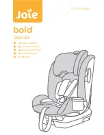
Bold
Brand: Jole Pages: 63

TEDDY BEBEPOD
Brand: 7 A.M. Enfant Pages: 2

06587
Brand: tuctuc Pages: 28

lottie
Brand: Kiddicare Pages: 10

front 2 backrider
Brand: Infantino Pages: 21

Marquee MM-0XXX-T
Brand: Exor Pages: 54

Jetson AN810
Brand: Aetina Pages: 13

AX720 Series
Brand: Aetina Pages: 24

Z603L/LE
Brand: RTimes Pages: 18

RTSO-9003
Brand: RTimes Pages: 17

Z509
Brand: RTimes Pages: 19

RTSO-9003U
Brand: RTimes Pages: 21

RTSO-6003
Brand: RTimes Pages: 26

MYRA
Brand: KIKKA BOO Pages: 26

Side Rider Baby Carrier I
Brand: Infantino Pages: 4

Unison series
Brand: Infantino Pages: 6

carry on
Brand: Infantino Pages: 2

Support
Brand: Infantino Pages: 6


