ACME NEBULA, User Manual
Introducing Theatrelight NEBULA - a groundbreaking lighting control system that revolutionizes stage performances. With its intuitive interface and quick operation, you'll effortlessly create mesmerizing lighting effects. For easy convenience, download the comprehensive user manual for free at manualshive.com and unleash the full potential of NEBULA's extraordinary capabilities.
Share
Download


Reviews:
No comments
Related manuals for NEBULA

1720
Brand: 3M Pages: 9

L23
Brand: DBPOWER Pages: 30

Access XL E Series
Brand: OCULUS Pages: 8

NOBO X20P
Brand: ACCO Brands Pages: 33
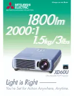
XD60U
Brand: Mitsubishi Pages: 2

MX805ST
Brand: BenQ Pages: 28

NOBO S17E
Brand: ACCO Brands Pages: 38

CablePort desk
Brand: Kindermann Pages: 2

LED Profile C34
Brand: Light Sky Pages: 28

TheaterLite DXG-210
Brand: Zenith Pages: 13

TS542
Brand: Optoma Pages: 1

Starlino
Brand: Reer Pages: 44

CD-725c
Brand: BOXLIGHT Pages: 33

VirtuaLine SWITCH LED
Brand: Laserglow Pages: 13

AccuVar NEMA 4X
Brand: Emerson Pages: 2

500 Series
Brand: Emerson Pages: 12

IE Series
Brand: Emerson Pages: 12

Interceptor II TVSS
Brand: Emerson Pages: 4


