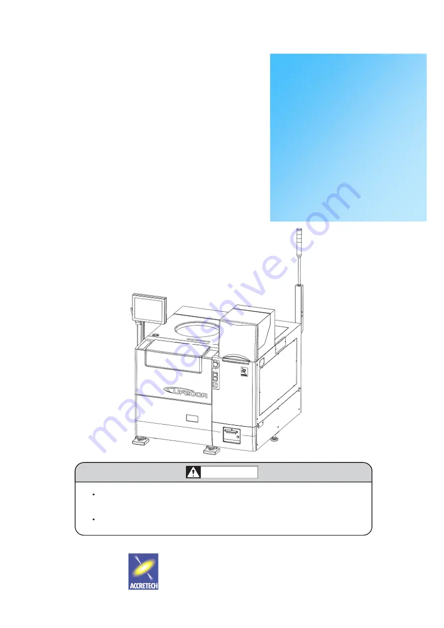
background image


FULLY AUTOMATIC 

PROBER


UF200R 
UF190R 

USER’S MANUAL


- OPERATION -


TOKYO SEIMITSU CO., LTD. 

Before operation, be sure to read this manual and obtain
full knowledge about this device through training.
Keep this manual safely in a specified place.

WARNING

Document No.  : FT32000-R001-E0
Date Issued 

: 2010-05-26


Summary of Contents for UF200R

Page 1: ...NUAL OPERATION TOKYO SEIMITSU CO LTD Before operation be sure to read this manual and obtain full knowledge about this device through training Keep this manual safely in a specified place WARNING Docu...

Page 2: ...e For this reason it should be noted that some of the descriptions in this manual may not apply to your particular system depending on its configuration Prepared by Prober System Group Hachioji Plant...

Page 3: ...on Contact with a moving transfer arm may result in serious injury Keep the loader cover closed during operation When using the optional HF test head manipulator Dropping of the upright head stage may...

Page 4: ...contents of this manual Costs of consumable parts as well as for spare parts labor and transportation for maintenance past the warranty period shall be borne by the customer Damages and liabilities W...

Page 5: ...CH will not be liable for damages resulting from the use of such components and parts Furthermore even if the components and parts were acquired from ACCRETECH or its suppliers ACCRETECH will not be l...

Page 6: ...tion settings 2 4 2 2 Device Data Switching 2 5 2 2 1 Saving deleting device data 2 7 2 3 Probe Card Replacement 2 8 2 4 Wafer Alignment 2 11 2 4 1 Manual registartion of models 2 13 2 4 2 Manual Alig...

Page 7: ...ocessing 5 2 5 2 Overdrive Amount Modification 5 3 5 3 Confirmation and Correction of Probe Mark Position 5 4 5 4 Probe Mark Display 5 5 5 5 Sequence Back 5 6 5 6 Multi Pass Probing 5 7 5 6 1 Tips for...

Page 8: ...Contents III 6 14 Make User File 6 8 6 15 System Reset 6 9 7 APPENDIX Prober Status Display...

Page 9: ...ce 1 2 1 2 EMO and POWER Switches 1 3 1 3 Display Touch Panel Unit 1 4 1 4 Head Stage 1 5 1 5 Storage Media 1 6 1 5 1 Floppy Disk Drive FDD 1 6 1 5 2 USB terminal 1 6 1 6 Internal Printer Optional 1 7...

Page 10: ...ation for the following operation points The startup procedure from power up to staring of operation is also explained Operation points for UF200R UF190R 1 EMO emergency stop and POWER switches 2 Load...

Page 11: ...s and Startup 1 2 1 1 Appearance The external appearance of a standard specification UF200R system is shown below Loader Display Touch panel Head stage Internal printer optional Storage media EMO swit...

Page 12: ...ly to the prober will be shut off immediately and all moving parts will be stopped the ON switch lamp will dim and the OFF switch lamp will be lit To recover from this power down status unlock the EMO...

Page 13: ...play touch panel unit can be adjusted by loosening the clamp knob on the support joint Display Touch Panel Screen The screen displays information such as the prober status and control parameters It al...

Page 14: ...one hand completely loosen the two clamp bolts Caution The head stage is spring loaded and will automatically begin to lift once the clamp bolts have been loosed To avoid the head stage from jumping...

Page 15: ...front panel For normal prober operations it is not necessary to use a USB terminal as the device data control parameter can be written to the internal hard disk drive However you will need to use thes...

Page 16: ...tional An internal printer which is an option is installed on the lower left part of the Prober front The print head is in the upper portion and the paper roll holder is in the center You can feed pri...

Page 17: ...ction tray are performed with buttons on the display touch panel Touch the NEW CST button to process new cassettes and the Lock Unlock button to lock unlock the inspection tray To set a wafer onto the...

Page 18: ...egistered as part of the Prober Configuration Data Engineer level data can contain the password for the Engineer level only Manager level data can contain a password each for both the Engineer level a...

Page 19: ...2 2 1 1 Switching the display with the Screen Change button 2 3 2 1 2 Operation settings 2 4 2 2 Device Data Switching 2 5 2 2 1 Saving deleting device data 2 7 2 3 Probe Card Replacement 2 8 2 4 Wafe...

Page 20: ...ace after the completion of prober startup 1 Screen display and operations prior to starting lot processing 2 Switching of device data 3 Replacement and management of prober cards 4 Wafer alignment Fo...

Page 21: ...ting screen Card Change button Turn this button on before replacing the probe card Screen Change button Switches the display on the screen between Prober Status Lot Information and Loader Status When...

Page 22: ...e cassette and the results are displayed for each slot as either Unprocessed or WF Nothing Unprocessed wafers will be labeled with a wafer ID or a wafer No after testing The slot numbers are assigned...

Page 23: ...g are set to STOP the prober will pause after processing each wafer Load Unload Position is used to specify the point on the chuck at which the wafers are loaded and unloaded Touch the ENT button when...

Page 24: ...the parameters will be overwritten with the new settings To check the settings for the Device parameters use the Previous Page and Next Page buttons to browse through the parameter display pages Touch...

Page 25: ...reen the device data file for the specified device name is not found you can search for the file by touching the Device List Reference button at the lower left of the screen This will display a list o...

Page 26: ...ins a file of the same name you will be asked whether or not to overwrite the existing file with the new device data Touch the ENT button to overwrite and the CANCEL button otherwise When the data is...

Page 27: ...Lot Information Loader Status screen before starting the lot processing touch the Card Change button to display the Card Change screen On the Card Change screen turn on the Card Change Start button Th...

Page 28: ...e returned to the Card Type Data menu The Card Data Delete button will delete a registered card type when touched Index Size X Y X and Y index sizes for the dice of Multi Test Sites Touch to display t...

Page 29: ...nd Needle Cleaning Count will be reset to zero Data for all registered cards are stored along with their contact count and needle cleaning count data Therefore if a previously used card is loaded its...

Page 30: ...s on the screen and manually register suitable patterns as models Once the initial wafer of a new device has been aligned the used models will be saved as part of the device data Alignment for later w...

Page 31: ...Reset button Resets the current X Y position to zero so as to measure the distance moved by the chuck Function Switch Disp SW displays buttons along the bottom of the screen such as Auto Brightness Se...

Page 32: ...adjust the chuck position so that a pattern appropriate as a low magnification mode is displayed within the window at the center of the screen The pattern must be unique within the range of 1 index in...

Page 33: ...es may be difficult to recognize Not good No horizontal edges Good However the white are may become too bright for recognition Not good Pad patterns may become marked upon contact with the probe and r...

Page 34: ...ck moves and the die pattern from the right edge of the wafer will be displayed on the screen Locate a unique point along the same die row as the first point use the arrow keys to align this point wit...

Page 35: ...s on the pad registration 3 13 3 3 Pad Alignment 3 15 3 3 1 Manual needle alignment teaching 3 16 3 3 2 Confirming the needle alignment results 3 17 3 4 Contact Height Determination 3 21 3 4 1 Executi...

Page 36: ...ioning table and can be moved up or down independently of the chuck s Z axis F axis The position and size of each pad are registered in advance using the wafer alignment camera After determining the p...

Page 37: ...so be calculated from the probe heights measured during pad alignment While this method does not require the probes to contact the wafer the standard procedure is to manually leave a probe mark on a p...

Page 38: ...in printer External Printer means optional external printer and Internal External Printer means both shared printer With FD needle alignment result is saved in an exclusive file automatically created...

Page 39: ...e Alignment Fine Adjustment Data X Y Needle Alignment Die Coordinates X Y in the Needle Alignment Data Settings menu are re written by the values optimized during the automatic needle alignment proces...

Page 40: ...n of the needle height determination result by the operator will be awaited Upper Limit of Auto Needle Height When Assort Of Auto Needle Height Setting above is set to TTL or GP IB the probe card may...

Page 41: ...adjustment die becomes impossible and Z Axis Soft Error or Drive Range over results If the die used for contact check when automatically adjusting the needle height can be used as wafer center die se...

Page 42: ...cribed below may occur in the worst case To avoid such damage make an alignment with the actual needle height of the probe card When the needle height is unknown set a large value to avoid damage 1 Wh...

Page 43: ...enter or the group center of registered pads For a multi site card the site center can be judged from the corresponding die center or the center of pad group for the site Probe Card Center Offset X Y...

Page 44: ...Pad Edge With 0 entered no check for the tip position Tolerant Error of Needle Tip Focus Posi The allowance of probe height variation for the measurements by Auto focusing If the variation for a card...

Page 45: ...remains fixed However by specifying the search range probe tip images are searched corresponding to pad location by moving the view Low MAG Needle Alignment Mark Settings One of the function of AS200...

Page 46: ...right corner at first and then the lower left corner must be entered Operate Joy Stick to align the die upper right corner to the hair crossing lines in the view Then push Data in button the screen c...

Page 47: ...height When pads are made of Aluminum that shines in the pattern PAD SEARCH button can make the window automatically determine the location and sizes of a pad existing near the window Otherwise operat...

Page 48: ...ion process as shown left one pad group near a die corner and another group near the corner diagonal to the first corner in order to ensure reliable and faster alignment for all the probes and pads Fo...

Page 49: ...nification alignment processes Then the display again changes to the screen shown in the fourth Next pad and Previous Pad buttons make the individual registered pads brought up in the screen center At...

Page 50: ...s shows that the probe tip images are compared and fitted to the pattern of a registered pad group In the high magnification view each probe tip is reviewed while changing the camera height to determi...

Page 51: ...cross mark to under the cross mark and push Data in Then the images of probe tips corresponding to those pads in another side of die are shown also together with the alignment cross mark Adjust the i...

Page 52: ...the die lower left corner of the die appears in the center of the screen accompanied with the cross mark Pushing Next Pad button will bring the next pad into the screen center with the cross mark also...

Page 53: ...erances on the corresponding pads This indication Mode selection is applied to the printout of probe pad alignment result too Touching Mag Change button in the right side of the screen makes the high...

Page 54: ...finish of the pad alignment processes See Page 3 4 DEVICE Device name INDEX Index sizes X Y ORI FLA Orientation flat angle XY LIMIT 1 Tip position allowance from the pad edge XY LIMIT 2 Tip position a...

Page 55: ...ill start the wafer theta alignment to fit the pads to the detected probe tips and then the pad alignment will finish Pushing Card Check Utility button brings back the pad alignment confirmation scree...

Page 56: ...up Chuck by 5 m and sends Test Start signal with Contact Check Request signal again This cycle is repeated until FAIL signal has not come when Tester judges that probe tips have contacted to pads The...

Page 57: ...ight determination has finished the display changes to the screen shown left If this stop is not demanded with the parameter probing starts according to the preset wafer map with the preset overdrive...

Page 58: ...ot positioned under the card at the contact height determination its site No disappears After the probe mark check push EXIT button the display changes to the wafer map indication screen and probing s...

Page 59: ...er is kept to 1 meaning that the die thus chosen is contacted by Site No 1 probes After the selection push Data in button the display changes to the probe mark reconfirming screen as shown upper left...

Page 60: ...4 2 1 Setting the test die area 4 5 4 3 Reference Die Setting 4 6 4 3 1 Target sensing 4 8 4 3 2 Difference between TEG and corner targets 4 10 4 3 3 Setting the reference die 4 12 4 4 Die Attribute S...

Page 61: ...nd or the Data in operation on the reference die may be demanded depending on the parameter setting Results of these operations are saved in the Device data file so they are unnecessary at the later l...

Page 62: ...Reference die setting Probing start Automatic process Manual operation Wafermap attribute change Necessary assist Data in operations on the end dice of each column or rowat Direct Range Setting or on...

Page 63: ...while viewing the die row or column on the display or through the microscope At the beginning of probing for a new device the Data in operation is demanded 4 Point Data In is to set the area by appoin...

Page 64: ...s specified as forced marking will be forcibly marked Example of forced marking skipping dice setting when the measurement area is set by 4 point Data In is shown in the figure on the left Method For...

Page 65: ...ws the screen for teaching the end dice of each test die column or row when the view is fixed to the low magnification With Joy Stick set to INDEX mode bring each column row end die under the cross ma...

Page 66: ...ference die coordinates on Setup Sequence Settings sub menu Page 1 3 of the Basic Operational parameters See 3 4 Setup Sequence Settings in Control Parameters USER S MANUAL When Teaching or Target Sen...

Page 67: ...ference die means to give the reference coordinates to die column and row in the test area edges so the corner die is a virtual die located on a crossing point of the extended die column and row Among...

Page 68: ...die block Target verifying area The target sensing procedure is 1 After completion of the wafer alignment of the Device initial wafer a model image is taken on a normal testing die and its position in...

Page 69: ...h range when the die whose location is determined in Relative Coordinates X Y Center Origin for Target Sense Die on Page 2 3 is not TEG input range 0 to 50 mm Search range R R X and Y Index R X or Y I...

Page 70: ...st in a block choose a corner TEG die and a corresponding verification method so that the verifying 2 x 2 die block does include only one TEG die In a case of a 2 x 3 TEG die block as above for the up...

Page 71: ...ng the first located die as shown below at right which is fixed independently of the parameter Target Search Range X Y sides 1 indexes TEG Model search area TEG target Unwanted target Corner target Mo...

Page 72: ...cified Data in operation for the target sensing model is demanded as shown on the left in the middle Find out within the die area of a normal test die the most unique pattern that has no similar patte...

Page 73: ...ands for the forced marking die At using the optional Periphery Marking function the number of forced marking dice may increase depending on its setting With Marking Die Setting set to Dice by Data in...

Page 74: ...tton of Marking Die Skip Die Needle Inspection Die or Normal Die the attribute representing character changes accordingly At setting Method of Die Attribute Selection to Camera Image the view of the w...

Page 75: ...Device initial wafer the Data in on sample dice will be demanded At the end of the sample die selection the contact height determination process will begin With the parameter set to Sample Regular th...

Page 76: ...choose blocks of die for sampling test see the figure below applicable at the single site probing only Down Loading is not effective at present Sampling Die Selection With the top DATA IN At Sampling...

Page 77: ...ctly with Method of Die Attribute Selection set to Map Display Move the cursor to a wanted die by direction key and push Sampling Die button the test die mark T will change to SP mark to indicate a sa...

Page 78: ...t Processing 5 2 5 2 Overdrive Amount Modification 5 3 5 3 Confirmation and Correction of Probe Mark Position 5 4 5 4 Probe Mark Display 5 5 5 5 Sequence Back 5 6 5 6 Multi Pass Probing 5 7 5 6 1 Tips...

Page 79: ...result for each die Use the OUT and IN buttons at the upper left part of the screen to zoom in or zoom out The map can be scaled in four steps After manually stopping probing or resetting an error th...

Page 80: ...he other parameters are not accessible once lot processing begins To change the overdrive amount you can also use the Needle Align Pos Correct button on the text map screen as explained on the followi...

Page 81: ...e parameter Probing Overdrive alone as shown below Other buttons on the contact height manual adjustment screen Image Display Change Touch this button twice to move the chuck to below the alignment ca...

Page 82: ...d with serial No 1 is displayed in high magnification by the die of site No 1 tested last time To confirm the needle mark of other pad adjust the die position using the direction key Using the multi s...

Page 83: ...the pad registration probe mark inspection utility screen as shown at left in the second Touch Mag Change button to change the display to high mag Choose the pad by operating the direction key Touch...

Page 84: ...nment Retry to measure and align the wafer again Upon completion of alignment the wafer will be tested starting from the start die If the automatic probe pad alignment function is provided Needle Pos...

Page 85: ...ngs will open Multi Pass Probing Operation Settings sub menu Page 1 1 Dice for Multi Pass Probing Selection of retesting dice from a test result wafer map the all dice tested previously Fail dice only...

Page 86: ...ter Start of Probing 5 8 Sum Up of Multi Pass Probing For the wafer or lot summary data to be printed the selection either both of the previous test results and the re testing results or the re testin...

Page 87: ...d take care of the wafer numbering in the lot management 4 Before beginning the re probing insert the floppy disk containing the map data of the target lot into the Prober s FDD and set Input Map Data...

Page 88: ...again there will end the utility operation Output Map Data Choose Yes Output Map Data To Choose FD Output Format of Map Data Select TSK Standard Recovery At Output Error Select Alarm Stop When correla...

Page 89: ...t Select Alarm Stop except when lot number can be identified with the wafer ID Clear Lot At Lot End Select Yes except when lot number can be identified with the wafer ID Touching Combination of Wafer...

Page 90: ...Touching this button will bring up the Multi Pass Probing Setting screen In the upper line select Multi Pass Probe For the marking mode in the lower line All Fail Die makes all Fail dice after the OR...

Page 91: ...tility 6 4 6 5 Date Time Setting 6 4 6 6 Internal Printer Status Display Switching 6 4 6 7 Cleaning Utility 6 5 6 8 Task Version 6 5 6 9 Test Count Display 6 6 6 10 Reject Counter Reset 6 6 6 11 Data...

Page 92: ...the idle state touch the Utility button at the upper right of the Wafer Map Prober Status or Lot Information screen to switch to the Utility menu page 1 3 On the menu screen touch a function selection...

Page 93: ...rring an inspection tray containing a cleaning or correlation wafer into the specialized tray Select the source and destination for the transfer and touch the Transfer Start button to transfer the waf...

Page 94: ...he tester by this manual Test End operation Test Complete indicates that a Test Complete signal has been received from the tester and Tester Busy indicates that the tester is in use Test Result displa...

Page 95: ...floppy disks and the hard disk 2 Deletion of unwanted data files 3 Formatting of floppy disks 6 5 Date Time Setting Use this screen to set the date and time of the prober s internal clock Click on a...

Page 96: ...ean the probe tip with the cleaning unit or the cleaning wafer as per the cleaning parameters When the Cleaning Counter Clear button is touched the screen shown on the left is displayed Select the cou...

Page 97: ...a the Previous Wafer and Next Wafer buttons allow you to switch between tested and untested wafers within the current lot The Cassette No Slot No and Wafer No values will be updated accordingly Max 4...

Page 98: ...eration Parameter The corresponding parameter menu is displayed 2 Touch the parameters you wish to hide on the menu screens and they will change color to red 3 Touch the Setting End button on the menu...

Page 99: ...rameters will affect ALL devices The Make User File function allows you to select up to 50 Basic Operation parameters and include their settings in Device parameter data files When the prober operates...

Page 100: ...etting screen At this point do not touch the Data Store button 3 Open the Operation Settings screen and touch the Prober Mode Setting button to display the Basic Operation parameter setting screen Cha...

Page 101: ...APPENDIX Prober Status Display...

Page 102: ...the prober status wafer map lot information or loader status display Perform the necessary recovery operation Alarm lamps buzzer and on screen messages indicate the various operation statuses as desc...

Page 103: ...Operator call Power up Start button ON initialization ALARM OFF key NEW CST switch Startup screen waiting for the Waiting for the card center without using the automatic pad Waiting for a FOUP Orange...

Page 104: ...y A 3 Warning condition Start button ON Probing continues ALARM OFF key ON Recovery actions ALARM OFF key ON Alarm stop System error Power supply OFF ON resetting Operating steps conditions Green lamp...

Reviews: