

Installation Instruction
ABB Automation Products GmbH
Eppelheimer Str. 82
69123 Heidelberg, Germany
Phone: +49 62 21 701 1444
Fax:
+49 62 21 701 1382
E-Mail: [email protected]
www.abb.com/PLC
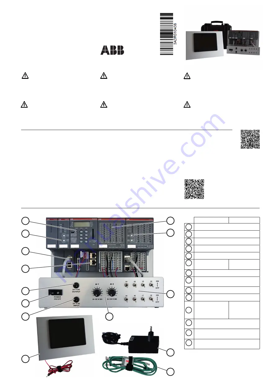
System setup
Take system out of the case and place upright.
Connect the power adapter (13) to the wall socket
and the cable plug to the power input socket (2).
Connect the panel (12) power supply cable to the
output socket (3). Connect an Ethernet cable (14)
on one side on panel (12) Ethernet socket ETH0
and the other side to the terminal base Ethernet
socket (11). After switching on the power switch
(1), the system starts loading the PLC and the
panel program. The system is now ready to use
the demo program.
Warning!
This training case is a class A device for EMC,
because the main components (e.g. PLC) inside
are designed for industrial applications. It can
cause radio-interference in residential areas.
Warning!
The operating temperature for training case is
0 °C … + 40°C
Warning!
This training case must only be used with the
delivered power supply adapter. The use of
another power supply is prohibited.
Warning!
This training case is only intended to be used
by skilled persons aware of the risks using
electrical equipment and knowing the techni-
cal rules, codes and relevant standards.
Important!
Please refer to the “Regulations concerning the
Setting up of Installations” for safety instruc-
tions.
http://search-ext.abb.com/library/Download.
aspx?DocumentID=3ADR025003*&Action=Launch
Warning!
This training case is only intended to be used for
demonstration and training activities, and it must
not be used for industrial applications.
Features of demo program
The demo is ready for use when the CPU display is
showing „run“ and the panel screen shows „CP600-
Pro Demo Project“. Touching „Training Case“ opens
the visualization of the input states of the I/O chan-
nels. The input status on the screen changes when
potentiometer (4) or switches (5) are operated. The
demo program in the PLC reads inputs and copies
the input state to outputs. On the I/O modules can be
observed that the status LED of outputs are following
the input status. Touching the house symbol (upper
right corner) closes the demo visualization. The other
buttons on the panel screen open demos for features
of the panel.
Restoring demo program
The training case is delivered with demo program
installed. If needed, the demo program can be
restored from the SD card. The QR code opens the
operation instruction explaining configuration of
components and procedure for loading the demo
program into PLC and panel.
TA515 CASE,
TA5450 CASE
7
8
5
4
6
10
11
9
3
1
2
12
14
13
TA515 CASE
TA5450 CASE
1
24V DC Power switch
2
24V DC Power input socket
3
24V DC Power output socket
4
2 Potentiometers
5
8 Switches
6
CPU PM583-ETH
CPU PM5630-
2ETH
7
Analog/digital I/O module DA501
8
Communication interface
module CI502-PNIO
9
Communication module CM579-PNIO
10
PROFINET connection
11
TB521-ETH
Ethernet Plug
ETH1 for Panel
connection
TB5620-2ETH
Ethernet Plug
ETH2 for Panel
connection
12
Panel with power supply cable
13
Power adapter
14
Ethernet cables and SD card containing
demo program


