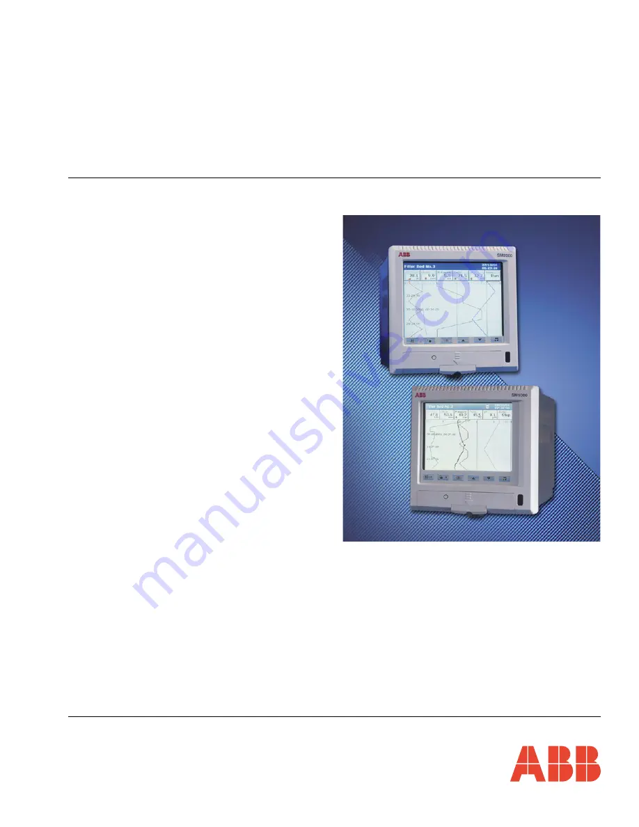
background image

User Guide Supplement –
Advanced Software Options

IM/SM2000ADV

Issue 7

Videographic Recorders

SM1000 and SM2000

Summary of Contents for SmartMedia SM2000

Page 1: ...User Guide Supplement Advanced Software Options IM SM2000ADV Issue 7 Videographic Recorders SM1000 and SM2000...

Page 2: ...vative design and development to incorporate the latest technology The UKAS Calibration Laboratory No 0255 is just one of the ten flow calibration plants operated by the Company and is indicative of o...

Page 3: ...9 Standard Functions 11 2 9 1 Trigonometric Functions 11 2 9 2 Statistical Functions 11 2 9 3 Logarithmic Functions 11 2 9 4 Relative Humidity 11 2 9 5 Sterilization Fvalue Calculation 13 2 9 6 Switch...

Page 4: ...tems in the Configuration system s menus see Fig 1 2 SM2000 recorders with the optional math equations and logic editor functionality are identified by the appearance of the respective icons in the ma...

Page 5: ...1 Each math block comprises any number of sources constants operators and functions to a maximum length of 40 characters see Fig 2 1 page 4 Possible operators sources and functions are listed in Tabl...

Page 6: ...math block e g to evaluate the equation proceed as follows Enter math block 1 as m1 a1 a2 m2 Enter math block 2 as m2 52 4 a3 Digital signals md1 to md3 are evaluated as 0 inactive and 1 active thus...

Page 7: ...pped or reset Available only on analog channels and if the relevant totalizer is enabled in the Configuration level Minimum Statistics Input Value Stats 1 1 min to Stats 2 6 min sl11 to sl26 Value sin...

Page 8: ...nt sample N 1 to 9999 samples T 1 to 9999 seconds Sd x n t Standard Deviation of variable x over n samples at a sample rate of t seconds N 1 to 200 samples t 1 to 9999 seconds Logarithmic Functions se...

Page 9: ...ches Math Pad see Fig 2 3 Select math blocks 7 to 12 Return to Main Math Block screen see Section 4 6 2 of the User Guide Deletes the function operator or source to left of cursor Clears the whole equ...

Page 10: ...Source Digital Source 1 Set the digital source e g alarm signal real time event used to reset the equation Select the digital signal e g alarm signal real time event used as Digital Source 1 md1 withi...

Page 11: ...and SM2000 2 Math Configuration IM SM2000ADV Issue 7 9 Fig 2 4 Worked Example Note A digital signal must be assigned to a digital source before it can be selected as a Math block source see Reset Sour...

Page 12: ...Low 50 0 Note For the best resolution enter engineering ranges to the maximum permissible number of decimal places Enter the tag name to be displayed on channel indicators and used to identify the ch...

Page 13: ...d psychrometer having an air velocity of at least 11 5 feet per second or 3 5 meters per second across the bulb sensors Inputs used for wet and dry bulb measurement must be in the ranges 0 to 100 C or...

Page 14: ...ers SM1000 and SM2000 2 Math Configuration 12 IM SM2000ADV Issue 7 Fig 2 6 Relative Humidity Calculation Select the RH function Select the wet bulb source Select the dry bulb source Set the engineerin...

Page 15: ...ning sterilization time by accumulating credit for the time spent approaching and receding from the sterilizing temperature It is important to note the large change in equivalent sterilizing time whic...

Page 16: ...14 IM SM2000ADV Issue 7 Fig 2 8 Sterilization Fvalue Calculation Select the Fo function Select the temperature source Enter the target temperature Select a digital source such as an alarm to reset th...

Page 17: ...ar flow device such as Vortex Swirl Ultrasonic Turbine and Magnetic Flowmeters 2 Using a differential pressure transmitter across an orifice plate or wedge Corrections can be applied to compensate for...

Page 18: ...olume Flow Average Density Constant Temperature Compensation Fig 2 12 Temperature and Density Compensation h V Q 1 tr tb a Qma Qc x Da Qmm Qc x Dm Qmd Qc x Dd Qc Derived density correction Where V Lin...

Page 19: ...be achieved on the DP device or on the input set up of the recorder Let m1 constant 1 x a3 Qc m2 a1 x constant2 x a2 m1 Note Input a3 is the actual product temperature input as a2 in previous examples...

Page 20: ...ms 1 1A 1 1B and 1 2A monitor the reservoir level Digital output D6 to drive the control valve from Logic Equation 1 Digital input D1 to operate the manual override Fig 3 1 Logic Equation Example Alar...

Page 21: ...n operator for the next input Select Logic Equations 7 to 12 Inputs A 0 0 1 1 B 0 1 0 0 Operators Outputs All inputs high AND 0 0 1 1 Any or All input s low NAND 1 1 1 0 Any or All input s high OR 0 1...

Page 22: ...M2000 Fig 4 1 Math Block Diagnostics Fig 4 2 Logic Equation Diagnostics Value when key last pressed Press to display values and result based on most recent calculations Only configured math blocks can...

Page 23: ...mentation pH Conductivity and Dissolved Oxygen Transmitters and Sensors Ammonia Nitrate Phosphate Silica Sodium Chloride Fluoride Dissolved Oxygen and Hydrazine Analyzers Zirconia Oxygen Analyzers Kat...

Page 24: ...ontinuous product improvement and the right is reserved to modify the information contained herein without notice Printed in UK 01 09 ABB 2009 ABB Limited Howard Road St Neots Cambridgeshire PE19 8EU...

Reviews: