ABB RELION REL670, Product Manual
The ABB RELION REL670 Operator's Manual is a comprehensive guide designed to assist users in operating this powerful and advanced product. Available for free download on our website, it provides detailed instructions and information to optimize the performance of your REL670. Get your free manual at manualshive.com.
Share
Download


Reviews:
No comments
Related manuals for RELION REL670

BD163T
Brand: hager Pages: 2

AccuVar ACV Series
Brand: Liebert Pages: 13

UM Series
Brand: STI Pages: 18

EuroProt+
Brand: Protecta Pages: 10

ke-DP01
Brand: E.K.T. Pages: 4

Home Theatre P52926
Brand: RCA Pages: 4

50ML8105D - Quickuse
Brand: Magnavox Pages: 2

50ML6200D - 50" Rear Projection TV
Brand: Magnavox Pages: 41

PELTOR Optime MT155H530A 380
Brand: 3M Pages: 94

SP10
Brand: Caleffi solar Pages: 4
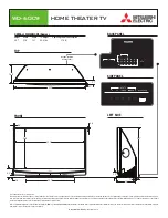
WD-60C9
Brand: Mitsubishi Electric Pages: 1

Pro-Anchor PA-132-EV
Brand: Omni cubed Pages: 13

GBE-100A
Brand: Geobrugg Pages: 41

GBE-1000A
Brand: Geobrugg Pages: 41

Bard-Parker
Brand: BD Pages: 2

Projection HDTV
Brand: ARRI Pages: 38


