ABB MV3B1RN5CB, Instruction Manual
The ABB MV3B1RN5CB is a high-quality electrical component used in industrial applications. Unlock its full potential with our comprehensive Instruction Manual, available for free download from manualshive.com. Get all the technical information and guidance you need to maximize the efficiency of your operations with this user-friendly manual.
Share
Download


Reviews:
No comments
Related manuals for MV3B1RN5CB

ReLy OSSD2
Brand: SICK Pages: 36

R7M-RR8
Brand: M-system Pages: 4

SEL-351-5
Brand: Schweitzer Engineering Laboratories Pages: 706

MSF 220 SE
Brand: ZIEHL Pages: 4

SBM-LSG-IR
Brand: EOS Pages: 72

REX 521
Brand: ABB Pages: 32
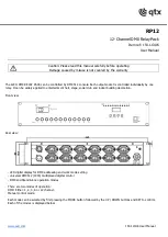
RP12
Brand: Qtx Pages: 4

EMT62-DB
Brand: Eaton Pages: 5

CL-AB-5AMR2
Brand: Climax Pages: 2

950-1040 24V RELAY KIT 8504052 REV. 3 1097
Brand: TJERNLUND Pages: 2

1 Relay Module
Brand: PXM Pages: 8

PX232
Brand: PXM Pages: 11

ADR141A
Brand: Ashida Pages: 151

ADR241B
Brand: Ashida Pages: 272


