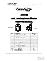
background image

LLT100

Laser Level Transmitter

Operating Instructions/OI-LLT100-EN Rev. D

The new standard in industrial laser 

level transmitters

Measurement made easy

Customer benefits

The LLT100 is specifically made for industrial applications 
and harsh environments. It provides continuous, non-contact 
level measurement capabilities for process automation 
and inventory management in industries such as mining, 
aggregates, oil & gas, chemicals, food & beverages, power, 
pulp & paper, pharma, and water & waste water.

Optimize process or inventory management


– Precise measurement of any solid or liquid


– Independent of material properties

Low cost of ownership


– Fast and flexible installation


– No maintenance


– Single product configuration works in many applications

Main features

ABB brings laser level transmitters to the next level of non-
contact measurements by packaging laser ranging technology 
with the features required by industrial applications. Using a 
pulsed laser for performing time-of-flight measurements, 
the LLT100 provides accurate distance measurements 
while being powered from the 4 – 20 mA loop. Available in 
aluminum or stainless steel body, it comes with a variety of 
process interfaces. It can meet the demands of hazardous 
area locations, as well as high pressure and high temperature 
applications.

Convenient


– Easy setup function


– Articulated embedded user interface


– 2-wire powered, and HART 7 communication

Reliable


– Dust and fog penetration capabilities


– Accurate measurements at short and long distances


– Explosion-proof class 1, division 1 (zone 1)

Summary of Contents for LLT100

Page 1: ...maintenance Single product configuration works in many applications Main features ABB brings laser level transmitters to the next level of non contact measurements by packaging laser ranging technology with the features required by industrial applications Using a pulsed laser for performing time of flight measurements the LLT100 provides accurate distance measurements while being powered from the ...

Page 2: ...n in the official ABB Inc Product Catalogs the latter take precedence ABB Inc reserves the right to make changes to the specifications of all equipment and software and contents of this document without obligation to notify any person or organization of such changes Every effort has been made to ensure that the information contained in this document is current and accurate However no guarantee is ...

Page 3: ... 12 Selecting the measurement mode 21 6 13 Configuring filtering options 21 7 Configuring filtering 23 7 1 Setting the rate unit 23 7 2 Configuring a No Measurement period 23 7 3 Configuring the median filter 23 7 4 Configuring the filling rate 24 7 5 Configuring the draining rate 24 7 6 Enabling damping 24 8 Configuring linearization 25 8 1 Defining linearization 25 8 2 Configuring device lineari...

Page 4: ...Area Consideration Labels 47 Ex Safety aspects and IP Protection Europe 47 Ex safety aspects and IP protection North America 49 Specific condition of safe use for ATEX IECEx and cFMus certifications 50 Instrument labels 51 Optional ID tag plates 52 Appendix B Accessories 53 Cooling tube 53 External commissioning laser device 55 Dust tube 55 Purge ring 55 Adjustable pivot bracket 56 Swivel mount 57...

Page 5: ...ns the solely binding warranty regulations in full These contractual warranty provisions are neither extended nor limited by the information provided in this manual Read this manual carefully before working with the instrument For personal and system safety and to obtain optimum performance make sure that you thoroughly understand the contents of this manual before installing using or maintaining ...

Page 6: ...trical circuit diagrams The electrical connection information in the manual must be observed otherwise the applicable protection type may be affected Ground the instrument according to requirements In addition you must observe the relevant safety regulations regarding the installation and operation of electrical systems and the relevant standards regulations and guidelines about explosion protecti...

Page 7: ... device during all procedures of operation as per IEC 60825 1 Ed 2 2007 It complies with FDA performance standards for laser products except for deviations pursuant to Laser Notice No 50 dated June 24 2007 1 5 Improper use It is prohibited to use the instrument for any including but not limited to of the following A climbing aid e g for mounting purposes A support for external loads e g as a suppo...

Page 8: ...This page intentionally left blank ...

Page 9: ...nly No user operator adjustments inside the LLT100 are necessary or recommended by the manufacturer For additional information or in the event of specific problems not covered in detail in this user guide please contact the manufacturer Moreover ABB declares that the contents of this manual are not part of any prior or existing agreements commitments or legal relationships nor are they intended to...

Page 10: ...This page intentionally left blank ...

Page 11: ...EMIs electromagnetic interferences are extremely present such as in rock quarries mines or in large chemical plants ABB recommends the use of noise filters on the DC power supply to the instrument and on signal isolators 4 20 mA output The same power supply can be used for both the 4 20 mA loop and the window heater A second pair of wires shall be used to avoid voltage drops exceeding the LLT100 e...

Page 12: ... an interval of several weeks increased force will be required to unscrew the housing cover This is not caused by the threads but rather by the type of gasket used WARNING Sharp edges Do not handle the instrument by the threaded interface Threaded edges are sharp and could cause personal injuries 4 Run the cable through the cable gland and the open port 5 Connect the positive lead to the terminal ...

Page 13: ...minal Surge protector equipped terminal block To ensure proper functioning ground connection is mandatory for surge protector equipped instruments An overloaded instrument must be de energized for at least 5 seconds CAUTION Test voltage withstand capability can no longer be ensured when this protective circuit is used Outside installations or installations exposed directly or indirectly to lightni...

Page 14: ... on the power source check the following Covers installation Locking screws tightness Process connections Electrical connections The LLT100 can then be put into operation NOTICE Brief interruptions in power supply will result in initialization of the electronics the embedded software restarts 3 5 1 Typical connections Figure 6 2 2 wires Figure 7 2 2 wires with heater option Figure 8 2 wires ...

Page 15: ... select numbers of a parameter value using the Up or Down arrow keys Figure 9 Typical User screen left and Configuration screen right Table 1 Left and Right arrow key functions Left arrow key Meaning Exit Exit menu Back Back one sub menu Cancel Exit without saving the selected parameter value Next Select next position for entering numerical values or letters Right arrow key Meaning Select Select s...

Page 16: ...value 4 2 1 Selecting an option You can select options but you can not modify them This is the easiest operation to perform 1 Using the four arrow keys move left or right up or down within a menu 2 Once you find the option that you want to set highlight it by using the arrow keys 3 Press OK The highlighted option is selected and effective immediately 4 Press Back repeatedly to exit the menu Figure...

Page 17: ...able Remote Transducer is a hybrid analog and digital industrial automation protocol Its most notable advantage is that it allows remote configuration of LLT100 instruments over legacy 4 20 mA analog device current loops sharing the pair of wires used by analog only host systems ABB provides a HART communication package for the LLT100 Once installed in your preferred HART application it will allow...

Page 18: ...This page intentionally left blank ...

Page 19: ...nd No measurement period 15 seconds 4 20 mA output PV Level PV unit Meter LLT100 failure alarm High 21 mA 5 Quick setup Figure 15 General model Sensor offset Vessel height Vessel full URV Vessel empty LRV Ullage Level The LLT100 can be configured with the integrated keypad controlled and menu driven LCD user interface Before setting up your LLT100 instrument it is important to know which value is ...

Page 20: ... all Easy Setup parameters have been set press Next to exit the Easy Setup menu and go back to the default Operator page 5 2 2 Setting volume parameters 1 Once the LLT100 is on access Easy Setup in the configuration menus and press Select 2 Select the interface language and press Next English is selected by default 3 Select the measurement mode and press Next Standard is selected by default You se...

Page 21: ...urface Positioning This mode features a special calibration designed to work with retroreflector panel targets provided by ABB It also features an enhanced double reflection detection algorithm Use for positioning applications where the sensor aims at a highly reflective retroreflector panel Note Only use when the target is a retroreflector panel For positioning applications with other types of ta...

Page 22: ...This page intentionally left blank ...

Page 23: ...Software WP screen press Edit and select On 3 Press OK 6 3 Setting measurement values The LLT100 can monitor four values These values are identified as primary PV secondary SV tertiary TV and quaternary QV The primary value PV is the only value directly linked to the 4 20 mA loop It impacts other parameters used by the instrument To set these values 1 From the Device Setup menu select Process Vari...

Page 24: ...value is the ullage value as measured from the top of the vessel The default value is 0 0 as ullage should be zero at calibration point 00 3 Press the Right arrow key to edit this value 4 Press OK once you are done 5 Press the Left arrow key again to select the Out value For calibration point 00 the Out value is the level value as measured from the bottom of the vessel The default value is the ves...

Page 25: ...onitored vessel To set the level unit 1 From the Device Setup menu select Level Units 2 In the Level Units screen select the unit m cm mm ft in and press OK 6 11 Setting the sensor offset The sensor offset as shown in Figure 15 General model on page 15 is the distance separating the LLT100 from the top of the vessel It represents the volume where solids or liquids can not accumulate This distance ...

Page 26: ...This page intentionally left blank ...

Page 27: ...eriod Enable 2 From the Enable menu select whether or not you want to enable the filter and press OK 7 2 2 Setting the No Measurement period To do so 1 From the Device Setup menu select Filtering No Measurement Period Period 2 From the Period menu edit the No Measurement period as necessary between 2 s and 99 999 s and press OK For dust or vapor applications enter a period corresponding to the typ...

Page 28: ... 5 Configuring the draining rate The draining rate corresponds to the maximum speed at which a vessel drains Its value is used to limit the maximum possible rate of change of the level measurement reading during drainage This feature is used in clear liquid processes where the bottom of the tank is visible through the surface and in liquid processes held in highly reflective stainless steel vessel...

Page 29: ... proper values this function allows to compensate for the irregular shape of the vessel 8 2 Configuring device linearization The linearization function available only in Advanced mode is always used to convert level to volume in all applications In tanks with an irregular shape you can enter between 2 and 21 linearization points The first point is always the point with the lowest value and all oth...

Page 30: ...n Configure Tables Save 2 From the Configure Tables screen press OK The linearization table is saved 8 3 2 Resetting to default linearization table If you modified the linearization table and realize that your configuration should not be saved it is possible to revert the default empty linearization table To revert to the default linearization table 1 From the Device Setup menu select Linearizatio...

Page 31: ...enu select Operator Pages Operator Page n n being the number of the operator page that you want to configure 2 From the Operator Page n screen select Display Mode Edit 3 From the edit page select the display mode and press OK There are eight modes available expressed as N x M where N represents the number of rows and M the number of characters Here are examples of display modes 4 Once the display ...

Page 32: ...Display menu select Security Set Standard Password or Set Advanced Password 2 In the password edit window use the Up and Down arrow keys to move left or right and highlight the alphanumerical characters that you need to create the password 3 Press Next to select the highlighted character and move on to the next character to highlight 4 Repeat steps 2 and 3 until your password is complete 5 Press N...

Page 33: ...see Setting measurement value high and low limits on page 19 Generally the High value will trigger this mode To set which alarm will trigger the failure mode 1 From the Process Alarm menu select Failure Mode 2 From the Failure Mode screen select High or Low to determine which alarm will trigger the failure mode 3 Press OK 10 2 Defining alarm delays A delay was implemented to prevent raising alarms...

Page 34: ...lect Process Alarm Limits Level or UIlage and the alarm level that you want to configure Low Low Low High High High 2 Edit the level as necessary Figure 20 illustrates that the Low Low value must be lower than the Low value and that the High High value must be higher than the High value The LLT100 will not allow you to enter values that do not meet this criteria 10 4 3 Enabling level and ullage al...

Page 35: ...asuring point from a measurement technology and safety point of view This applies with respect to Explosion protection certification Measuring range Temperature Operating voltage Moreover the suitability of the materials must be checked with regards to their resistance to the media This applies with respect to Gaskets Process connections isolating diaphragms mounting screws etc NOTICE Property dam...

Page 36: ...e 2 Measurement modes on page 17 11 4 Rotating the LCD When the LCD is installed it is possible to rotate that display in one of four different positions at 90 intervals CAUTION Property damage For Ex d and or flameproof installations see note Securing the housing cover in flameproof explosion proof areas on page 8 NOTICE Observe applicable ESD protection measures to avoid damaging instrument circ...

Page 37: ...its indicated previously may permanently damage the instrument To rotate the housing 1 With an Allen key unscrew the housing stop tang screw by NO MORE than one turn do not pull out the screw 2 Position the housing in a way that is optimal to you between 45 and 90 The tang screw rotates with the housing 3 Once the housing is in the proper position tighten the stop tang screw 11 6 Selecting install...

Page 38: ...owever for liquid applications mount the laser as perpendicular as possible to the surface A misalignment of up to 5 degrees may be acceptable in very good conditions short distance smooth surface clear light but the longer the distance the more perpendicular the laser must be no more than 1 or 2 degrees for optimal performance To prevent interference with nearby objects the instrument output lase...

Page 39: ...tice No 50 dated June 24 2007 If too many obstacles are present around the beam path the external commissioning laser device can help to align the LLT100 To use the device 1 Make sure two AAA type batteries are in the device 2 Install the external commissioning laser instrument on the process flange or bracket and screw it in place 3 Turn on the external commissioning laser device and verify the a...

Page 40: ...e OI LLT100 EN Rev DE LLT100 Laser level transmitter 11 8 Installation Do s and Don ts Figure 27 Recommendations for installation in solid vessels P P Figure 28 Recommendations for installation in liquid vessels P ...

Page 41: ...leaning the window all models BUT hygienic on page 37 When installed in a dusty environment the LLT100 must be equipped with a dust tube This will ensure long term reliability and performance It is recommended to perform periodic inspections of the lens The higher the dust level or environmental exposure the more frequent these inspections should be NOTICE Always turn the power off before removing...

Page 42: ...s 3 Remove the window O ring 4 Clean the window the O rings the flange adapter and the flange Replace the O rings if damaged NOTICE Do not dismantle the window Opening the instrument voids the warranty 5 Lay down the flange on the table and install the O ring 6 Screw the instrument on the flange by hand 7 Make sure that the window O ring remains well in place 8 Tighten firmly with the hook wrenche...

Page 43: ...OI LLT100 EN Rev D User Guide 39 Figure 31 Hygienic flange window assembly Flange Notch Window O ring Flange O ring Adapter flange Notch Locking set screw 4 ...

Page 44: ...This page intentionally left blank ...

Page 45: ...n the error number is displayed in the second line for example F204 042 The next two lines are used to describe the error The two last digits of the error number correspond to the error code described in Table 4 on page 45 In the example above F204 042 42 refers to the target lost error as also indicated by the error message WARNING Permanent Namur Process Error When F204 042 Target Lost Error is ...

Page 46: ...ument You can also obtain the HART version number by selecting Communication HART Revision 13 6 Managing Instrument Communications When your LLT100 is on a network you can set multiple connection parameters from the Communication menu 13 6 1 Editing the instrument address To modify the instrument address 1 From the Communication menu select Device Address 2 Edit the address and press OK 13 6 2 Sel...

Page 47: ...at are not free of hazardous materials acids alkalis solvents paints etc or dirt If you are unable to solve a problem contact ABB Service is only to be handled by authorized factory trained personnel Before contacting ABB please check the following All cables are properly installed All relevant troubleshooting steps outlined in this manual have been followed Refer to the back cover for contact det...

Page 48: ...ve 2012 19 EU or corresponding national laws e g the ElektroG Electrical and Electronic Equipment Act in Germany According to WEEE Directive 2012 19 EU only products used in private applications may be disposed of at municipal garbage facilities DO NOT use municipal garbage collection points for this purpose Dispose of the product or solution directly at a specialist recycling facility Proper disp...

Page 49: ... service 25 Electronics NV Syncing Information Contact ABB service 30 HMI Validation Test Failure Reset device Replace LCD if condition persists 31 Sensor Window Obstructed Dirty Clean window Contact ABB if condition persists 32 Electronics Insuff Input Voltage Insufficient voltage to operate device 33 Amb Temp Out of Range Readings may be invalid due to improper ambient temperature Correct ambien...

Page 50: ...This page intentionally left blank ...

Page 51: ...th a Ta from 50 C to 85 C T6 Temperature class of the LLT100 corresponding to 85 C max with a Ta from 50 C to 75 C Gb Equipment protection level b for Gas atmosphere NOTICE The number indicated on the safety label close to the instrument CE marking identifies the Notified Body which has responsibility for surveillance of the production Certificate IECEx Ex db op is T6 Ga IIC T6 T5 Gb for LLT100 XX...

Page 52: ... T85 C T100 C Db IP66 IP67 for LLT100 XX A to G All flanges except Triclover FM Approvals certificate number FM16ATEX0032X The meaning of ATEX code is as follows II Group for surface areas other than mines 2 Category for instrument installed in Cat 2 zone 21 1 Category for laser aiming in Cat 1 zone 20 D Dust dangerous media Ex tb type of protection tb means protection by enclosure op is Da optica...

Page 53: ...sion 1 Groups B C and D hazardous classified locations Dust ignition proof for Class II and III Division 1 Groups E F and G hazardous classified locations T5 Temperature class of the LLT100 corresponding to 100 C max with a Ta from 50 C to 85 C T6 Temperature class of the LLT100 corresponding to 85 C max with a Ta from 50 C to 75 C Enclosure Type 4X applications indoors outdoors For proper field i...

Page 54: ... 85 C max with a Ta from 50 C to 75 C Specific condition of safe use for ATEX IECEx and cFMus certifications WARNING The LLT100 enclosure contains aluminum As such it is considered a potential risk of ignition by impact or friction Care must be taken during installation and use to prevent impact or friction Under certain extreme circumstances exposed plastic including powder coating and unearthed ...

Page 55: ...ATEX FM16ATEX0032X LASER LEVEL TRANSMITTER US Class I Division 1 Groups A B C D T5 50 C Ta 85 C US Class I Division 1 Groups A B C D T6 50 C Ta 75 C FM APPROVED US C Zone 21 AEx Ex tb op is Da IIIC T85 C T100 C Db 50 C Ta 75 C 85 C IECEx FMG 16 0023X II 2 1 G Ex db op is T6 Ga IIC T6 T5 Gb 50 C Ta 75 C 85 C II 2 1 D Ex tb op is Da IIIC T85 C T100 C Db 50 C Ta 75 C 85 C IP66 IP67 Class I Zone 1 AEx...

Page 56: ...nada www abb com level YYYY MM DD LLT100 XXXXXXXX LLT100 LASER LEVEL TRANSMITTER DETECTEUR DE NIVEAU LASER PROTECTION ENCL Type 4X IP66 IP67 PROCESS PRESSURE bar POWER SUPPLY ALIM OUTPUT SIGNAL SORTIE HEATER SUPPLY ALIM 3W 15 5 42V ATTENTION WARNING Ne pas ouvrir en présence d atmosphère explosible Lire le manuel attentivement pour les consignes de sécurité Do not open in presence of explosive atm...

Page 57: ...22 P923 and P924 right Tables on the next page indicate the need for air flow based on cooling tube model process generated temperatures and ambient temperature NOTICE The cooling tube is not a pressurized vessel As such it should not be exposed to air pressures exceeding 10 psi 0 7 bar Also to prevent air pressure build up the bottom air outlet should NEVER be blocked in any way If a tube extensi...

Page 58: ...si 0 6 bar Tube model Ambient temperature C Air flow needed minimum recommended flow if needed Air pressure at cooling tube air inlet P921 20 30 40 50 Max process temperature C 175 85 No 150 Yes 1 scfm 0 50 psi 0 05 bar 180 Yes 2 scfm 1 25 psi 0 1 bar Yes 3 scfm 2 75 psi 0 2 bar Yes 4 scfm 6 25 psi 0 45 bar Tube model Ambient temperature C Air flow needed minimum recommended flow if needed Air pre...

Page 59: ...er against dust Figure 43 Purge ring Figure 44 Dust tube and purge ring Purge ring Dust tube External commissioning laser device If too many obstacles are present around the beam path the external commissioning laser device can help you align the LLT100 For more information see section 11 7 1 on page 35 Figure 41 External commissioning laser device Laser Dust tube In applications where dust may be...

Page 60: ...ransmitter Adjustable pivot bracket The adjustable pivot bracket simplifies installation of the LLT100 at an angle Figure 45 Adjustable pivot bracket Figure 46 LLT100 on adjustable pivot bracket Figure 47 Typical LLT100 installation in dusty environments ...

Page 61: ...100 EN Rev D User Guide 57 Swivel mount The swivel mount allows rotation of the LLT100 around the laser axis Figure 48 Swivel mount parts left and completed assembly right Process flange Swivel mount assembly ...

Page 62: ... DN80 PN40 DN100 PN40 DN150 PN40 Material 304 Stainless steel Adjustable swivel mount Outer diameter 210 mm 8 3 in Mounting bolt pattern 3 bolt holes 10 mm 0 4 in diameter Tilt angle for aiming Continuously adjustable from 0 to 6 Material Aluminum Adjustable pivot bracket Overall dimensions 185 mm 7 3 in 249 mm 9 8 in 55 mm 2 2 in Opening diameter 60 mm 2 4 in Mounting plate thickness 5 mm 0 2 in ...

Page 63: ...flange 247 mm 242 mm 165 mm 9 7 in 9 5 in 6 5 in Hygienic flange 223 mm 237 mm 137 mm 8 8 in 9 3 in 5 4 in Weight of standard model Aluminum enclosure with universal aluminum flange 3 7 kg 8 2 lb 316L stainless steel enclosure with universal stainless steel flange 8 6 kg 19 0 lb Weight of pressure rated model Aluminum enclosure 6 7 7 2 kg 14 8 15 9 lb depending on flange 316L stainless steel enclo...

Page 64: ...idth 0 7 cm 0 3 in 2 0 cm 0 8 in 3 3 cm 1 3 in 6 6 cm 2 6 in 13 5 cm 5 3 in 20 cm 7 9 in 34 cm 13 4 in 69 cm 27 2 in 108 cm 42 5 in Beam direction 90 5 from mounting flange for measurements of liquids Environmental conditions Operating temperature 40 C to 60 C 40 F to 140 F up to 280 C 535 F with cooling tube Storage temperature 40 C to 85 C 40 F to 185 F Survival temperature 40 C to 80 C 40 F to ...

Page 65: ...OI LLT100 EN Rev D User Guide 61 Appendix D EU Declaration of Conformity For the latest EU declaration of conformity version please contact ABB ...

Page 66: ...This page intentionally left blank ...

Page 67: ......

Page 68: ... this document We reserve all rights in this document and in the subject matter and illustrations contained herein Any reproduction disclosure to third parties or utilization of its contents in whole or in parts is forbidden without prior written consent from ABB ABB 2017 AA012909 01 ABB Inc Measurement Analytics 3400 rue Pierre Ardouin Québec Québec G1P 0B2 Canada Phone North America 1 800 858 38...

Reviews: