background image

Medium voltage products 

Index

  1. Packing and transport 

4

  2. Checking on receipt 

4

  3. Storage 

5

  4. Handling  

5

  5. Description 

6

  6.  Assistance  and  maintenance 

29                   

  7. Accessories 

33

  8. Recycling 

38

  9. Routine inspections 

42

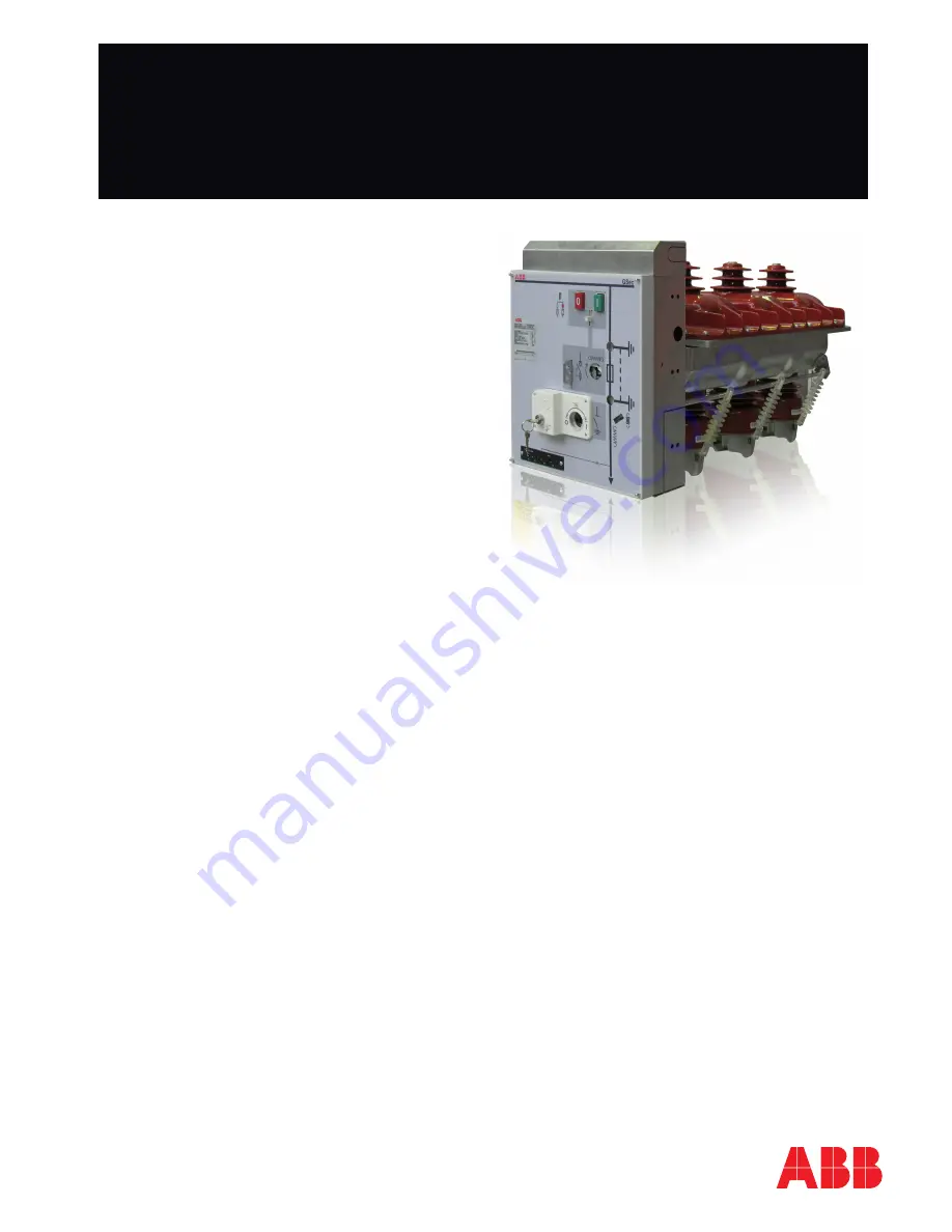
GSec 

Instructions for installation, operation and maintenance 

Summary of Contents for GSec/IB

Page 1: ...cking and transport 4 2 Checking on receipt 4 3 Storage 5 4 Handling 5 5 Description 6 6 Assistance and maintenance 29 7 Accessories 33 8 Recycling 38 9 Routine inspections 42 GSec Instructions for installation operation and maintenance ...

Page 2: ...ingle spring operating mechanism 21 5 13 2 Unit with double spring operating mechanism 23 5 13 3 No load spring release procedure 25 5 13 4 Operation of units with key interlocks 26 5 13 5 Cable testing 26 5 14 Putting into service 28 5 14 1 Preparatory operations 28 6 Service and maintenance 29 6 1 General recommendations and precautions 29 6 2 Maintenance frequency 29 6 3 Inspection 30 6 4 Assis...

Page 3: ... is not exceeded during service Pay special attention to the information in the manual highlighted by the following symbol Make sure that the personnel are provided with this manual and are aware of all the relevant information while operating on the apparatus Responsible behaviour safeguards your own and others safety Please consult us if further details if required Foreword The instructions in t...

Page 4: ...d The vehicle must also be covered with a tarpaulin 2 Checking on receipt Unload the switch disconnectors from the vehicle with the utmost care as described in chap 4 Immediately check the condition of the packaging as soon as the switch disconnectors arrive Make sure that the apparatus is undamaged and that the data on the nameplate on the outside of the packaging see fig 1 correspond to the info...

Page 5: ...he standard version and between 40 C e 45 C for the low temperature version Please consult us if special requirements are involved The switch disconnectors will have been strapped to the wooden pallet Cut the strap to unload the equipment For handling purposes the switch disconnector can be lifted by a crane fitted with ropes and snap hooks conforming to the safety standards to be fastened to the ...

Page 6: ...g mechanism 1S Single spring class M2 5000 mechanical operations Mechanical endurance of the line contact with operating mechanism 2S Double spring class M1 1000 mechanical operations Mechanical endurance of the earth contact class M0 1000 mechanical operations 1 630A for GSec T2 2 16kA 3s for GSec T2 3 For 21kA 3s please contact ABB 5 1 Performance and electrical characteristics Earthing switch t...

Page 7: ...or 2 Lifting points 3 Switch disconnector lever seat 4 Earthing switch lever seat 5 Switch disconnector position signalling seat 6 Rating plate Fig 2 7 Key locks 8 Voltage presence signalling lamps 9 Cable route of voltage presence signalling lamps 10 Terminal box of auxiliary circuits 11 Earthing circuit connection point 12 Main circuit connection point ...

Page 8: ...M10x25 141 5 141 5 A A 2 1 3 5 4 38 26 32 7 7 19 12 R 6 R 1 R4 R 2 R 2 R1 M6 through 2pcs 22 4 32 5 3 Overall dimensions GSec T1 T2 switch disconnectors Fig 3 Key 1 Upper contact 2 Upper contact 3 Low voltage enclosure 4 Housing of the operating mechanism 5 Enclosure GSec T1 24 06 20 17 08 20 12 08 25 GSec T2 24 06 16 Bearing surface Door interlock 10mm Travel 32mm Dimension required for door lock...

Page 9: ...ver seat 6 Terminal box for wiring auxiliary circuits 7 Switch disconnector position signalling seat 8 Earthing switch position signalling seat 9 Rating plate 10 Key locks 11 Voltage presence signalling lamps 12 Cable route of voltage presence signalling lamps 13 Three post and or capacitive insulators 14 Lifting points 15 Earthing circuit connection point 16 Main circuit connection point 17 Cable...

Page 10: ...8 26 32 7 7 19 12 R 6 R 1 R4 R 2 R 2 R1 M6 through 2pcs 22 4 32 180 5 840 150 238 238 238 581 272 5 320 180 5 150 UniSec SFC 375 Cubicle GSec T2F switch disconnectors Fig 5 Key 1 Upper contact 2 Lower contact 3 Low voltage enclosure 4 Housing of the operating mechanism 5 Cover 6 Fuse release system GSec T2F 24 06 20 24 06 16 17 08 20 12 08 25 Door interlock 10mm Travel 32mm Dimension required for ...

Page 11: ...h disconnector Earthing switch lever seat 6 Switch disconnector lever seat 7 Terminal box for wiring auxiliary circuits 8 Disconnector position signalling seat 9 Earthing switch position signalling seat 10 Rating plate 11 Key locks 12 Voltage presence signalling lamps 13 Cable route of voltage presence signalling lamps 14 Fixed contacts 15 Main circuit connection points ...

Page 12: ...R 2 R 2 R1 M6 through 2pcs 22 4 32 170 12 4 140 544 5 25 233 249 770 100 200 61 735 7 308 5 9 6x UniSec SBC 375 Cubicle GSec IB switch disconnectors Fig 7 Key 1 Upper contact 2 Lower contact 3 Low voltage enclosure 4 Housing of the operating mechanism 5 Enclosure GSec IB 24 06 20 24 06 16 17 08 20 12 08 25 Bearing surface Door interlock 10mm Travel 32mm Dimension required for door lock Fastening p...

Page 13: ...pes of GSec apparatus can be supplied GSec T1 three position switch disconnector with manual operation once dead center has been passed It is normally used to make incoming outgoing compartments GSec T2 three position switch disconnector with manual and stored energy operating mechanism It is normally used to make incoming outgoing compartments and can be equipped with shunt opening release GSec T...

Page 14: ...eeding dead center type It uses a single spring to open and close the switch disconnector and to close the earthing switch es Operating speed is independent of the operator Manual operating mechanism 2S is the stored energy type It uses two springs The first closes the switch disconnector at an operating speed independent of the operator The second spring is loaded during the switch disconnector c...

Page 15: ...thing switch ES 230 used in conjunction with the 1S operating mechanism is positioned on the load side of the safety circuit breaker associated with the IMS is interlocked by a transmission lever to earthing switch ST and has full making capacity Earthing switch EF 230 associated with operating mechanism 2S is positioned on the load side of the fuses is interlocked by a transmission lever and has ...

Page 16: ...nnect earthing switch ES 230 Comply with the following instructions when installing the earthing switch 1 Place the operating mechanism in its seat on the panel BOM Table Pos Description Q ty 1 Earthing switch EF230 375 1 2 ES Connection system 1 3 Screw ISO8678_M8X20 8 8 ZNBLC6 4 4 M8 Steel 6 flanged hex nut 4 Fig 10 Fig 11 Fig 12 Fig 13 Warning The spring must be fitted on top of the stud ...

Page 17: ...rds it means that the switch is in the open position DETAIL C 1 4 DETAIL B 1 4 DETAIL D 1 4 DETAIL W 1 3 U U 1 10 DETAIL V 1 2 4 Turn the switch to the earthed position 10 Adjust the ES connection system so as to obtain the necessary force and tighten the two nuts to the required torque value 9 The force measured 80 mm from the end of the blade must be 23 3 N 1 Assemble the Base 375 Fuse on the ri...

Page 18: ...itch 1 Assemble the fuse holder base on the right hand side of the panel There are two positions depending on the length of the fuse chosen Fig 16 Pos Description A0001 Q ty A0002 Q ty 1 Fuse base 1 1 2 Screw ISO8678_M8X20 8 8 ZNBLC6 8 8 3 M8 Steel 6 flanged hex nut 8 8 A0002 Assembly in the lower position for ABB 442 length fuses A0001 Assembly in the upper position for ABB 292 length fuses ...

Page 19: ...n the condition shown in figure 17 3 Position the two PVC spacers as shown in figure 18 and fix the switch lever to the two rods with the relative screw 4 Fix the switch to the panel with the relative screws as shown in figures 20 21 Fig 17 Fig 18 Fig 19 Fig 21 Fig 20 ...

Page 20: ...e open and the operating lever is withdrawn from its seat 5 10 Reference Standards IEC EN 60447 Man Machine Interface Actuating principles IEC 447 Direction of movement of electrical apparatus actuators CEI 17 4 Isolators and earthing switches for voltages over 1 kV IEC 129 Isolators and earthing switches for voltages over 1 kV IEC EN 60529 Protection classes of enclosures Classification IEC 529 P...

Page 21: ...hen using the operating lever turn it approximately 85 90 degrees to set the disconnector to the line position and 170 180 degrees for earthing Once started all the operations must be completed and the lever removed from its operating seat The operations must be performed with the normal actuating force using the dedicated operating lever 200 N If the operations are obstructed do not force the mec...

Page 22: ... into lower hole b Turn lever clockwise to earthed position 4 Switch disconnector opening from earthed position a Close cable compartment door Fig 25 Closed position Fig 26 Closed position with operating lever Fig 29 Earthed position with operating lever Fig 28 Fig 30 Earthed position Fig 27 Open position NOTE The cable compartment door can only be opened when the switch disconnector is in the ear...

Page 23: ...ble spring operating mechanism NOTE In the case of a motor operated unit with double spring operating mechanism all remote controlled operations must be inhibited and disabled before any mechanical operations are performed In the case of a motor operated unit with double spring operating mechanism it is advisable to push the pushbutton upwards to free the operating shaft hole before performing mec...

Page 24: ...hbutton to the left green O to set unit to the open position Fig 36 Open position Fig 40 Closed position Fig 41 Open position Fig 37 Closed position Fig 39 Closed position Fig 38 Open position f Push pushbutton to the right green I to set unit to the closed position The spring is now loaded d Remove the operating lever e Push pushbutton downwards to release pushbuttons arrow ...

Page 25: ...rtment door b Earthed position Fig 43 Earthed position Fig 44 Earthed position Fig 45 Earthed position with operating lever in lower hole Fig 42 Open position with operating lever in lower hole Fig 46 Open position NOTE The cable compartment door can only be opened when the switch disconnector is in the earthed position c Fit operating lever into lower hole d Turn lever counter clockwise to open p...

Page 26: ...kwise to release the motor 5 Remove the operating lever from the seat 6 Release the springs by means of the opening button 5 12 4 Operating units fitted with key interlocks The units can be fitted with key interlocks The key interlocks are available separately for both the line switch and earthing switch Key locks can only be used in the following cases The line circuit breaker can set to the foll...

Page 27: ...the earthing seat b Turn lever clockwise to the earthed position c Open cable compartment door d Remove the cover of the operating mechanism compartment e Push the locking plate into the upper position Fig 51 Earthed position Fig 52 Locking plate Fig 50 An example of key interlocks is shown in figure 48 The unit with single spring operating mechanism has 2 key interlocks for the line switch and 2 ...

Page 28: ...the efficiency of the mechanical and electrical interlocks without using force Check the SF6 gas pressure of the GSec switch disconnector and HD4 circuit breaker if available Set the required values for the protection devices in the switchgear and make sure they operate properly using test equipment Train local operators regarding the basic instructions for correct use of the switchgear Check to m...

Page 29: ...re pollution etc The maintenance intervals and measures to be taken given in table 18 are recommended for GSec switchgear under normal service conditions Three intervals per year are recommended for all maintenance measures in more demanding conditions such as areas with high pollution levels Switch disconnector 1S and 2S operating mechanisms are maintenance free and do not need any lubrication 6 ...

Page 30: ...must be taken if abnormal conditions are detected 6 4 Servicing Instructions If the need for servicing measures is established during the course of an inspection proceed as follows 1 Tighten all electrical connections to the correct torque value 2 Clean all parts disconnectors release mechanisms motors etc with a vacuum cleaner and visually inspect them Clean all surfaces in general Lightly settle...

Page 31: ...means of the striker pin s of the fuse s and the tripping mechanism Fig 53 Position indicator Fig 54 Fuses installed Fig 55 Fuses disassembled Instructions Check that the colour of the fuse indicator is red and that the position indicator is in the open position Turn the switch to the earthed position see chapter 5 12 Switch disconnector operating instructions Open the door The upper and lower fus...

Page 32: ...rt of the fuse into the bottom fuse holder Fig 56 Installing the fuses Fig 58 Fuses installed front c Push the upper part into the top fuse holder e Close the door f Turn the switch disconnector to the open position and then to the closed position see chapter 5 12 Switch disconnector operating instructions d Turn the fuse until the arrow and technical data texts are no longer pointing towards the ...

Page 33: ...Fujian Nanping Anda Electrical Manufacture Co Ltd is recommended for phase comparison Threshold values for voltage presence indication The indication corresponding to voltage present appears when the effective line to earth voltage is between 45 and 100 of the rated voltage The indication corresponding to voltage present does not appear when the effective line to earth voltage is less than 10 of t...

Page 34: ... 2 Interrogates the monitoring device the following information can be displayed OK correct operating pressure Low low pressure minimum level for operation Very low insufficient pressure operation cannot be performed These indications can be displayed remotely by means of 2 contacts built into the device Pressure gauge The device detects the measurement in temperature compensated zones and monitor...

Page 35: ...ting mechanism of the switch disconnector The mechanical Key 1 Interlock 2 Screw 3 Nut Door interlock 10 mm travel 32 mm dimension required for door lock Fig 62 interlock between the operating mechanism and door only allows the door to open when the earthing switch es is are closed force interlock Vice versa it prevents the operating mechanism from being operated if the door is open prevention int...

Page 36: ...hing switch for GSec T2F Key 1 Circuit breaker open closed key lock 2 Disconnector and earthing switch key lock Fig 63 7 5 Spare parts additional materials and lubricants 7 5 1 Spare parts Available on request A parts list for procurement of spare parts is available on request This list includes moving parts and parts subject to wear The serial number of the relative switchgear or switching device...

Page 37: ...thed position Check that the auxiliary power supply is connected Combined switch fuse unit Combined switch fuse unit will not close Check to see whether a fuse has blown Check that the lever is not in the operating hole Check that the locking part is in the down position Combined switch fuse unit is impossible to operate even though a fuse has blown Check that the fuse has been correctly fitted wi...

Page 38: ...rushed by mechanical means Information about suitable facilities can be obtained from the local environmental agency 8 2 Materials Product materials Table 21 gives examples of the SDC 375 unit materials and how they can be recycled Recycling capability Material Recyclable kg Steel Yes 106 5 69 Stainless steel Yes 5 5 3 5 Copper Yes 14 9 Brass Yes 0 5 0 5 Aluminium Yes 4 3 Zinc Yes 1 5 1 Plastic Ye...

Page 39: ...M12 97 M16 215 Cheese head Torx Fastite screw Max tightening torque Nm Type Steel class 8 8 M6 20 Cheese head hex socket screws Max tightening torque Nm Type Steel class 8 8 M4 2 M5 4 M6 8 M8 12 M10 35 M12 50 M16 110 Hex socket head and Torx round head screws Max tightening torque Nm Type Steel class 8 8 Steel class 10 9 M4 2 2 M5 4 4 M6 8 8 M8 12 12 M10 30 M12 60 The values in the tables must be ...

Page 40: ...8 16 56 nominal max 3 5 20 70 2 Bolts on electrical jaw contacts min 8 nominal 9 max 10 3 Cable connection nut min 18 35 65 170 nominal 20 40 70 180 max 22 45 75 190 4 Connections in busbar min 18 35 65 170 nominal 20 40 70 180 max 22 45 75 190 5 Bolts on circuit breaker min nominal 30 40 max ...

Page 41: ...6 6 Bolts on the Mandolino CT min nominal 35 max 7 Bolts on post insulator min 25 nominal 9 20 30 max 31 8 Bolts on connection and switching busbar min 56 nominal 20 60 max 70 9 CT mounting bolts min nominal 40 max 10 GSec and busbar HySec min nominal 35 max ...

Page 42: ...cription of the fault and reference data allowing the device to be identified etc Refer to article 10 of standard IEC EN 60694 if further details are required Do not hestitate to call us if problems arise It is always a good idea to inspect the apparatus screw and bolt tightness abnormal heating etc a few months after it has been put into service The following table gives the indicative frequencie...

Page 43: ...43 ...

Page 44: ...ers More service information abb com service 1VCD601151 Rev A en Instruction manual 2018 04 GSec gs Data and illustration are not binding We reserve the right to make changes in the course of technical development Copyright 2018 ABB All rights reserved For more information please contact ...

Reviews: