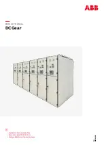
background image


DCGear

PRODUCT MANUAL 

DCGear

• High active and passive safety
• Internal arc proof 50 kA 250 ms
• High availability and low maintenance

Summary of Contents for DCGear

Page 1: ... DCGear PRODUCT MANUAL DCGear High active and passive safety Internal arc proof 50 kA 250 ms High availability and low maintenance ...

Page 2: ......

Page 3: ...5 016 022 023 024 025 030 031 031 034 1 General information 2 Receiving handling and storage 3 Installation 4 Technical characteristics 5 Preliminary checks and controls 6 Commissioning 7 Maintenance 8 Recordings 9 Accessories and spare parts ...

Page 4: ...re also upon proper installation and maintenance by the user The purpose of this manual is to assist the user in the main operations of installation use and maintenance of the appliance 1 1 2 Qualified personnel For the purposes of this manual it means a Qualified Person who has experience in the installation use and maintenance of the equipment and knowledge of the risks inherent therein In addit...

Page 5: ...an cause death or serious injury De energize and always ground the equipment and circuits connected to it before performing any maintenance To avoid risk of electric shock and impact with the mechanical parts moving at high speed this equipment must be installed operated and maintained by qualified personnel familiar with the product documentation and the system The use of non original spare parts...

Page 6: ...t of Make sure that the packaging is intact and free from damage during shipping If not noted on the delivery note PACKAGE DAMAGED THE POSSIBILITY OF DAMAGES TO THE MATERIALS CONTAINED doing counter sign the note to the carrier and immediately warning the ABB sales office about the damage occurred in transit Keep the damaged material for the carrier s inspection Do not proceed if you do not open t...

Page 7: ...ry to provide a storage for some time prior to installation it is advisable to store the equipment in its original packaging 2 4 1 Environmental conditions of storage 2 4 1 1 Storage in original packaging If possible store the panel in their original packaging Packing in wooden crates or cardboard Store in an environment protected from the weather covered well ventilated area with temperatures bet...

Page 8: ...maintenance operations In case of need the panels are delivered with rear doors completely screwed In this case it is possible to minimize the free space in the back leaving a corridor of escape 8 DCGear PRODUCT MANUAL Table 1 Dimensions and weights Height H Width W Depth D Installation and operation space R1 Installation and operation space R2 Weight Protection degree IEC 60529 Low voltage conpar...

Page 9: ...ent In general can be provided Tunnel for the cables for the auxiliary circuits command and control in the front of each compartment Tunnel for the power cables 3 2 2 Installation on floating floor Can be installed panels on dedicated floating basement with adjustable feet sized to support the weight of the whole panels and equipment on trolley In this case the power and auxiliary cables will have...

Page 10: ...10 DCGear PRODUCT MANUAL Fig 3 2 Fixing detail Fig 3 2 ...

Page 11: ...the support surface temporarily secure the structure to the support surface 11 INSTALLATION Connect adjacent sections inserting the screws M8 supplied in the holes drilled on the side of each compartment When required by the technical documentation assemble the kit of isolation between compartments placing the crosspieces and using insulating washers fig 3 3a Tighten the bolts Connecting bars betw...

Page 12: ...12 DCGear PRODUCT MANUAL Fig 3 3a Compartment coupling Fig 3 3a Bolt M8 Junction uninsulated ...

Page 13: ...13 INSTALLATION Fig 3 3b Compartment coupling coupling bars detail Fig 3 3b Screw head Nut A D A ...

Page 14: ...able trays and grounded ducts are half of those recommended between the cable trays In addition it is recommended to avoid long stretches in parallel cable trays or tunnels related to cables different level Any shielded cables must be installed by connecting to ground the sheath of the screen at one end only by the cable itself Table 2 Torque Table 3 levels of electrical signals Table 4 distance b...

Page 15: ... glands Reassemble the plates and then proceed with the passage of the relevant cables After the header proceed to connecting cables to the bar making sure not to decrease in any way the insulation distances 3 4 3 Grounding the electric panel The copper bar which extends for the entire length of the electric panel identified with the symbol PE is set for the connection of the individual ground con...

Page 16: ...or bolts Also panels and partitions will be realized with plates 2 mm of minimum thickness and fixed by bolts All the metallic parts will be connected to the earth collector The metallic parts of the withdrawable equipment remain connected to the earth also in the test disconnected and between each position An earthing bar will be provided along the whole switchboard internal sides An adequate con...

Page 17: ...Earthing circuits Protection degree Dimensions WxDxH Weight according to the cub config Ambient temperature range Altitude VDC VDC VDC kV kA kA kA ms kA IP mm kg C m 750 900 1800 6 9 1500 1800 3000 9 2 up to 6 up to 6 90 250 50 IP20 Cubic IP4X LV Comp 600x1600x2105 500 to 700 5 40 1200 4 3 Environmental condition The environmental conditions refer to the micro environment in which equipment is ins...

Page 18: ...bove two drawings show when the HSCB is in different positions of service test and disconnected the indicator will pointing to different directions When the trolley is going to the test position from outside it s needed to insert the operation lever into the button of the front panel which shows in the drawings and move it to the 45 direction in order to come out the groove The permission position...

Page 19: ...tion is locked and the HSCB is allowed to be closed When the trolley reachs the position it is needed to move the lever to the direction of which the picture shows before closing the HSCB The lower door of the panel has two sets of lockers The upper one is used to lock the test position as be showed in picture above rotating the key will cause the latch to be plugged into the notch on the cam to l...

Page 20: ...f which the picture shows before closing the HSCB The lower locker is used to lock the service position as be showed in picture above rotating the key will cause the latch to be plugged into the notch on the cam to lock the route Therefore before the trolley wants to go it has to unlock the locker first For the trolley to shuttle from test to service inserting the lever into the cam and operate it...

Page 21: ...nd or surge arrester where applicable The access is from the rear part by removable panel or door 4 6 2 Low voltage compartment This compartment contains the logic module of MS protection and control relay the low voltage components and all the other equipment necessary to realize the control and signaling circuit The access will be provided from the front through a door ...

Page 22: ...Feeder with Line DS Feeder with Earthing Switch Feeder with Bypass DS Feeder with Bypass DS and Line DS Main busbar Main busbar Main busbar By pass busbar By pass busbar Main busbar Main busbar Main busbar Line test Line test Gpro Line test Gpro Line test Gpro Line test Gpro Gpro Gpro ...

Page 23: ...trolley switch and the mechanism of movement of the shutters are perfectly cleaned Check that the power bus bars and power cable connections are clean Verify that the output connections of the panel are correct as indicated by the documentation Make sure that the equipment at low voltage is correct paying particular attention to the relays and protective devices Check the insulation of the auxilia...

Page 24: ...e been correctly assembled and fixed All trolley are in the isolated position with the auxiliary circuits connected properly In the circuit breaker compartment the space heaters have worked for at least 24 hours to ensure that there is no moisture in the ceramics contained it arc chute All protection relays are properly set to the values defined by the plant Feed then the auxiliary circuits of the...

Page 25: ...ts with a good and regular maintenance The maintenance intervals indicated below shall be understood as indicative The effective maintenance intervals depend on the environmental conditions and the characteristics of the system and must be defined on the basis of the staff experience of the Service and Maintenance of the effective needs of the service Even you need to keep in mind also the environ...

Page 26: ...of the protective cover to rotate the lock lever counterclockwise as shown in the drawings With the lever in this position you can open the shutters by hand Clean and grease the earth bars in zone of contact with the sliding contacts of the circuit breaker and the rectifier Clean and grease the mobile main contact check the correct torque of screw M8 and the mobile contact is aligned with the fixe...

Page 27: ...d mechanical parts in movement brusque The activity requires action in the high voltage cell De energize all circuits Use proper precautions Cleaning and lubricating mechanical parts Activity Condition safety instruction Risks Perform a thorough cleaning and adequate lubrication of all the mechanical parts subject to movement and in particular the advancement device the drive shaft of the earthing...

Page 28: ...cted try to remove it from the cell without lifting the locking pin to check that this is in grip Verify the correct operation of the interlocks of rectifier trolley Put the rectifier trolley in position disconnected try to remove it from the cell without lifting the locking pin to check that this is in grip Repeat if possible the same operations in the connected position Verify that the key locks...

Page 29: ...ety instruction Risks WARNING Possible tripping protection Before making this operation make sure that the control system of pts being in safety position The auxiliary circuits of command and control such as relays auxiliary switches buttons lamps etc generally do not require maintenance but only regular checking of their functionality SHEET 15 Test the functionality of the equipment through the f...

Page 30: ... Replace the damaged parts Replace with spare parts Verify converter settings Replace with spare parts Possible repair Replace with spare parts Item Motorization Voltage current transducer Compartment levers round bars Type of mulfunction Malfunction of the mechanical and electrical parts Damage to the electrical parts and malfunction of the measuring system Malfunction of the mechanical and isola...

Page 31: ...ows manual closing of the circuit breaker Enables you to keep in the rotated position the arc chute for easy maintenance of the contacts Allows the insertion of the circuit breaker in his cell Identification TZA6130C01 42810130B01 TZA5881CR1 42840209B01 8 Recordings WARNING When working on fixed parts inside make sure that the various factors which can get in touch even accidentally are made out o...

Page 32: ... 8 OUT Modicon M238 connexium ethernet interface for Interfaces connection telefast 12L 6 2O Connection sud base for twido extension 16 inputs Analog input module Operator pannel advanced touchscreen Power supply module M340 24 V DC 16 8 W Discrete input module M340 16 INPUTS 24 V DC Identification 62291521B01 AR747LT 62291521B02 CC20SRC120QF0020 MCR3E 1 5N THYD3X3 260 416 74 7030 RSPO 240 39OHM50...

Page 33: ...nd motorized moe T4 T5 24 Vdc T MAX Ciurcuit breaker 2 poles 6 A Curve K S 282 UC K6 Ciurcuit breaker 2 poles 10 A curve K S 282 UC K10 Ciurcuit breaker 2 poles 25 A curve K S 282 UC K25 Ciurcuit breaker 2 poles 2 A curve C S 202 M C2 Ciurcuit breaker 2 poles 4 A curve C S 202 M C4 Ciurcuit breaker 2 poles 10 A Curve C S 202 M C10 Ciurcuit breaker 2 poles 16 A curve C S 202 M C16 Ausiliary CONTACT...

Page 34: ...p Yellow lamp Blue lamp Whole bright body completo with Whole bright body completo with Whole bright body completo with Whole bright body completo with Whole bright body completo with Fixed base with contacts1no Blocco contatti con flangia 1NO 1NC Ausiliary contacts 1NC Identification 2966676 105CI 050PE8 CAD32ED ZB4BA4 ZB4BD2 ZB5AD5 ZB4BG2 ZB4BV01 ZB4BV03 ZB4BV04 ZB4BV05 ZB4BV06 ZB4BVBG1 ZB4BVBG3...

Page 35: ......

Page 36: ...ent Quebec Canada H4S 1N6 Phone 1 514 332 5350 Fax 1 514 332 0609 Email pes ca abb com ABB Sp Zo o Power Conversion 27 Placydowska Str 95 070 Aleksandrow Lodzki Poland Phone 48 42 24 00 100 Fax 48 42 29 93 340 Email enviline pl abb com ABB Sécheron SA Rue des Sablières 4 6 CH 1211 Geneva Switzerland Phone 41 58 586 22 11 Fax 41 58 586 23 05 Email info abbsecheron ch abb com ABB China Customer Serv...

Reviews: