background image


Page 1


© 2023 ABB. All rights reserved.


CC1600SC55_QSG


Rev 4.0


CC1600

-

SC55 Small Cell 

-

48V Power Source 


Document –


8600190737P


QUICK START GUIDE


Summary of Contents for CC1600-SC55

Page 1: ...Page 1 2023 ABB All rights reserved CC1600SC55_QSG Rev 4 0 CC1600 SC55 Small Cell 48V Power Source Document 8600190737P QUICK START GUIDE ...

Page 2: ...ifier 8 5 Ground the Rectifier 8 6 Open the Field Wiring Compartment 8 7 Wire the DC Output with Panel Option 1 9 8 Wire the DC Output with Panel Option 2 10 9 Wire the Alarms 11 10 Wire the AC Input 11 11 Close the Field Wiring Compartment 12 12 Apply AC Power and Confirm 48V Power Delivery 13 13 Attach the Solar Shield Cover for Solar Option 1 13 14 Attach the Solar Shield Cover for Solar Option...

Page 3: ... 6 Compression Connectors a U S or Canada installations use Listed Certified compression connectors to terminate Listed Certified field wire conductors b All installations apply the appropriate connector to the correct size conductor as specified by the connector manufacturer using only the connector manufacturer s recommended or approved tooling for that connector 7 Electrical Connection Securing...

Page 4: ... job training and safety procedures Use only properly insulated tools Remove all metallic objects key chains glasses rings watches or other jewelry Follow Lock Out Tag Out LOTO procedures customer specified site specific or general as appropriate Disconnect all power input before servicing the equipment Check for multiple power inputs Wear safety glasses Follow Personal Protective Equipment requir...

Page 5: ...ted in portrait orientation so that air can flow vertically by natural convection 2 Leave 3 inches above and below the unit to allow air to feed the fins and exit from the fins 3 If the mounting location has sun exposure a solar shield or cabinet must be used to protect the unit from direct sun 4 Mount the unit above the flood line Weep holes to equalize pressure and drain any water condensate tha...

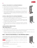
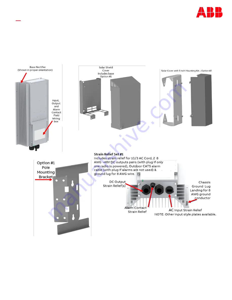
Page 6: ...dge as shown here C Drill holes to accept four 1 4 fasteners Use the Solar Shield Base as a template Vertical hole centers are 15 6 inches apart Horizontal hole centers are 10 4 inches apart p o Step 1 Wall Mount Shaded Locations With Shield Base Option 1 A Remove the Base Rectifier from the packaging B Select a location for the Small Cell Power Source Location should be above highest recorded flo...

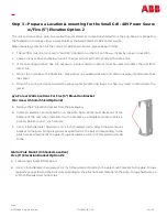
Page 7: ...er 5 Orient the wiring entrance toward the ground and provide drip loops to shed any water running down the jacket p o Pole or Wall Locations For Five 5 Elevation Bracket For Use with Solar Shield Option 2 A Remove the 5 Elevation bracket from the packaging B Select an elevation and orientation on the pole Note Wires must dress out of the bottom of the unit when installed Use the bracket as a temp...

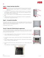
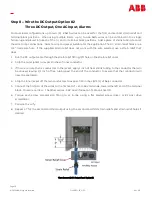
Page 8: ...on the lower right corner of the rectifier Use this location to provide external grounding as required by code or network standard 8 AWG minimum recommended ground wire Torque each nut to 26 in lbs Step 6 Open the Field Wiring Compartment The field wiring compartment is located on the lower third of the unit The front cover is secured by 4 captive screws The bottom cover that provides strain relie...

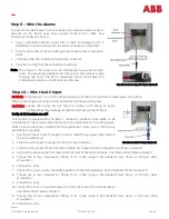
Page 9: ...er conductor 3 If there are more than 2 conductors in the jacket apply 1 inch of heat shrink tubing to the conductor that will be unused leaving 1 2 inch of free tubing past the end of the conductor to assure that that conductor will never be energized 4 Strip the inner jacket off the two conductors to expose 7 16 inches 11mm of bare conductor 5 Connect the first pair of the wires to the first set...

Page 10: ...f fitting left hole on the strain relief cover 2 Strip the outer jacket to reveal 2 inches of inner conductor 3 If there are more than 2 conductors in the jacket apply 1 inch of heat shrink tubing to the conductor that will be unused leaving 1 2 inch of free tubing past the end of the conductor to assure that that conductor will never be energized 4 Strip the inner jacket off the two conductors to...

Page 11: ...e a short circuit Verify all AC breakers are off The rectifier is designed for 10 AWG 3 conductor outdoor rated cable to be terminated in the terminal block located on the right side of the wiring space Select a wire and jacket suitable for the application Note 15A or 20A circuit protection is required 1 Run the AC input cable through the strain relief fitting lower right hole on the strain relief...

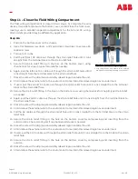
Page 12: ...e the strain relief fitting in the hole on the bottom cover using channel lock for snap in type strain relief as needed 11 Again pull the 2nd DC cable out through the strain relief hole until it runs straight from the terminal block to the strain relief hole 12 Dress the wire with a drip loop and visibly relaxed region outside the unit 13 Strain relieve the external wire to the environment to main...

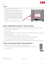
Page 13: ...y 1 Terminate insulate or protect the far end of the DC cables as these will be energized when AC is applied 2 Return to the AC panel feeding the unit 3 Unlock the panel 4 Energize the panel 120Vac 1200W max capacity 240Vac 1600W max capacity 15A or 20A circuit protection is required 5 Turn on the circuit breaker feeding the Small Cell 48V Power Source 6 Observe the LED illuminates green indicatin...

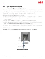
Page 14: ...ated contact closures relays rated at 60Vdc and 0 5A with 3 to 5 ms switching times Note Shell of RJ 45 connector must be shielded and grounded at both ends Note The outputs are common and electrically protected from short circuit Maximum current delivered is limited When the output is short circuited the unit will cycle on and off with a interval of about 14 seconds Short circuit hiccup is disabl...

Page 15: ... 3 Remove the ACCESS cover and disconnect wiring 4 Secure all wiring 5 Remove hardware holding the rectifier in position by removing the four hardware screws 6 Two installers shall remove the wall mounted or pole mounted unit 7 Install the retrofit unit and secure with the appropriate hardware 8 Install the electrical and dc output following removal using the installation procedure in reverse 9 Cl...

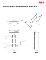
Page 16: ...Page 16 2023 ABB All rights reserved CC1600SC55_QSG Rev 4 0 Information Pole Mount Bracket Detail Drawing Mounting Option 1 FRONT VIEW SIDE VIEW ...

Page 17: ...Page 17 2023 ABB All rights reserved CC1600SC55_QSG Rev 4 0 Information Pole Mount Bracket Detail Drawing Mounting Option 2 ...

Page 18: ...t experience consistently higher lightning activity consider adding an external Surge Protective Device SPD consistent with region specific and network specific best standard practice Equipment Safety is Approved to UL6950 22 Equipment to be Installed Outdoors in environments with ambient temperature up to 46 C Equipment and subassembly ports 1 are suitable for connection to intra building or unex...

Page 19: ...Page 19 2023 ABB All rights reserved CC1600SC55_QSG Rev 4 0 Notes ...

Page 20: ...Page 20 2023 ABB All rights reserved CC1600SC55_QSG Rev 4 0 Version Date Description of the change 4 0 07 07 2023 Updated as per ABB template Change History excludes grammar clarifications ...

Page 21: ...t accept any responsibility whatsoever for potential errors or possible lack of information in this document We reserve all rights in this document and in the subject matter and illustrations contained therein Any reproduction disclosure to third parties or utilization of its contents in whole or in parts is forbidden without prior written consent of ABB Copyright 2023 ABB All rights reserved ABB ...

Reviews: