


—
A B B M E A S U R EM EN T & A N A LY T I C S | U S ER G U I D E | O I/FE A 10 0/ 2 0 0 - EN R E V. D
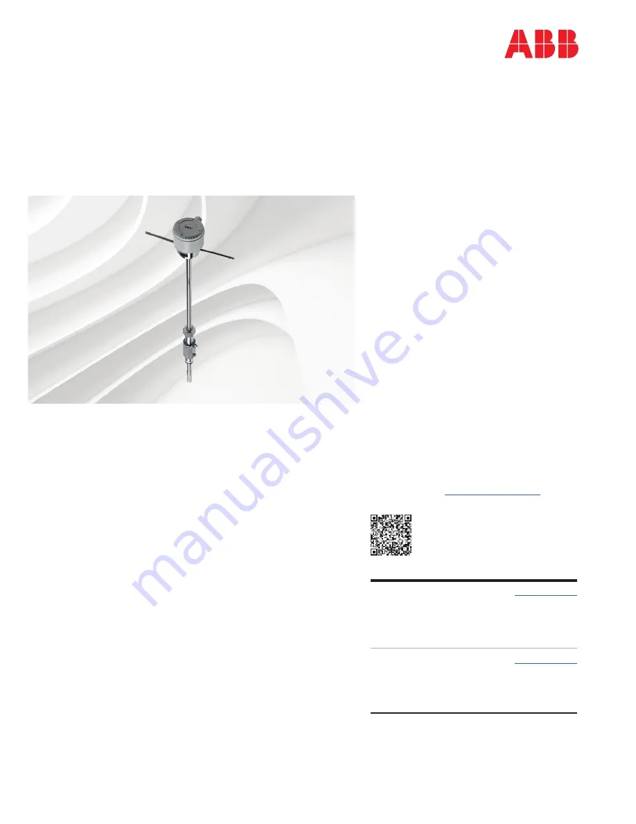
AquaProbe FEA100/FEA200
Electromagnetic flowmeter
insertion-type flow sensors
Maximum performance,
minimum hassle
Measurement made easy
Introduction
The AquaProbe FEA100/FEA200 flow
sensor is designed for measurement of the
velocity of water. The flow sensor is
available in four standard lengths and can
be installed in any pipeline of internal
diameter from 200 mm (8 in.) to 8000 mm
(360 in.), through a small tapping.
The flow sensor is designed for use in
survey applications such as leakage
monitoring and network analysis and in
permanent locations where cost or space
limitations preclude the use of conventional
closed pipe meters.
This User Guide provides installation,
connection, security, start-up and basic
setup details for the flow sensor only. The
AquaProbe sensor is available for operation
with either a WaterMaster transmitter
(FET100) or an AquaMaster3 transmitter
(FET200).
For more information
Further publications are available for free
download from
www.abb.com/flow
or by
scanning this code:
Search for or click on
Data Sheet
AquaProbe FEA200
Insertion-type electromagnetic
flow sensor with AquaMaster3
transmitter
DS/FEA200-EN
Data Sheet
AquaProbe FEA100
Insertion-type electromagnetic
flow sensor with WaterMaster
transmitter
DS/FEA100-EN
—
AquaProbe
FEA100/FEA200
flow sensor


