background image

— 

A B B ME A SUR EMENT & A N A LY TIC S | USER GU IDE | IM/A P20 0 R E V. S
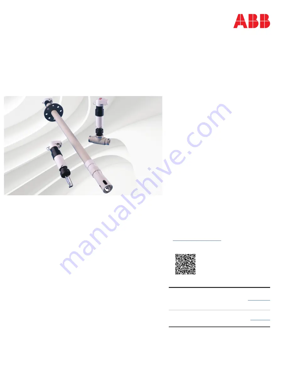
AP200 series

Rugged pH/Redox (ORP) sensor systems with rapid
temperature response for critical processes

Measurement made easy

Introduction

The pH / redox (ORP) sensor AP200 provides high 
reliability and withstands the toughest 
environments for process monitoring and control. 
The rugged assembly is built to bear the rigors of 
weather and process. Parts in contact with the 
process comprise chemically-resistant PPS Ryton™ 
and stainless steel, or PPS Ryton™ and Hastelloy C. 
Flow-through holders are available in polypropylene, 
while the PPS Ryton™ insertion adapter enables 
installation in alternative material pipelines. 
Insertion and Flow-through systems tolerate 
temperatures up to 130 °C (266 °F) and pressures up 
to 6 bar (90 psi). The inner electrode connections 
are ingress-protected to IP 67 / NEMA 6P (exceeds 
NEMA 4X). 

For more information

Further publications are available for free download 
from: 
 

www.abb.com/analytical


or by scanning this code:
 

Search for 
or click on

AP200
Rugged pH/Redox (ORP) sensor systems with 
rapid temperature response for critical 
processes
Data Sheet

DS/AP200-EN

AAO100
Dosing pump
User Guide

IM/DOSPMP

— 
AP200 series 
Rugged pH/Redox 
(ORP) sensor systems

Summary of Contents for AP201

Page 1: ...Hastelloy C Flow through holders are available in polypropylene while the PPS Ryton insertion adapter enables installation in alternative material pipelines Insertion and Flow through systems tolerate temperatures up to 130 C 266 F and pressures up to 6 bar 90 psi The inner electrode connections are ingress protected to IP 67 NEMA 6P exceeds NEMA 4X For more information Further publications are av...

Page 2: ...der in process automation technology we offer customers application expertise service and support worldwide We are committed to teamwork high quality manufacturing advanced technology and unrivalled service and support The quality accuracy and performance of the Company s products result from over 100 years experience combined with a continuous program of innovative design and development to incor...

Page 3: ...Model AP203 Flanged DIp Immersion System 7 2 3 System Assembly 8 2 4 Jetwash System 9 2 5 Jetwash System Assembly 10 3 Electrical Installation 11 3 1 Analyzer Connections 11 3 2 Shortening the Connection Cable 11 3 3 Extending the Connection Cable 12 3 4 Jetwash System Connections 12 4 Calibration 13 4 1 Method 13 4 2 Buffer Solutions 13 4 3 Redox ORP Sensor 13 5 Maintenance 14 5 1 General Cleanin...

Page 4: ...ucer to inform recipients of the information requirements when a candidate list substance is contained within an article at percentage of greater than 0 1 W W The candidate list substance acrylamide a substance of very high concern CAS 79 06 1 is totally enclosed within the gel component of the product and should pose no risk to the user during installation use and decommissioning providing the pr...

Page 5: ...ss steel adaptor Dimensions in mm in Fig 2 1 Model AP201 Insertion System ø50 327 12 87 100 3 94 15 min 15 min 90 3 54 G 11 4 G 11 4 G 11 4 R 11 4 or 11 4 NPT ø25 50 1 97 40 1 58 ø25 ø36 ø25 ø36 1 in NPT or R 1in 20 0 78 18 0 71 G 11 4 18 0 71 50 1 97 50 1 97 Pipe Mount System Tank Mount System Mounting Adaptors 7690 130 PPS Ryton R11 4in Adaptor 7690 134 PP 11 4in NPT Adaptor 7690 129 PP R11 4in ...

Page 6: ...low sufficient height above the system to enable the sensor to be withdrawn from the tee piece Dimensions in mm in Fig 2 2 Model AP202 Inline System 67 5 2 66 Minimum clearance required Stainless Steel versions only Polypropylene versions only To prevent spillage when system is removed To ensure electrode is always in sample Isolating Valve Isolating Valve Typical Installation Rp 1 in Female Threa...

Page 7: ...liding flange is supplied to enable adjustment of the immersion depth A suitable mounting bracket or support must be supplied by the user Dimensions in mm in Fig 2 3 Model AP203 Flanged Dip Immersion System 100 3 94 90 3 54 74 2 91 ø50 ø56 Thumb screws see Note below Mounting Flange Dimensions Mounting bracket supplied by user Insert 1 2 or 3 m 39 37 78 74 118 11 Typical Installation Note Ensure t...

Page 8: ...els AP201 Insertion and AP202 Inline Systems Fig 2 4 Models AP201 and AP202 Removing the Sensor Holder AP201 AP202 1 3 4 2 Open cover and detach cables and jetwash tubing if fitted from cap Twist cable shroud counter clockwise and remove Unscrew sensor holder retaining nut and remove sensor holder from in line adaptor Check O ring is in position located on underside of electrode holder ...

Page 9: ...e below Open cover and detach cables and jetwash tubing if fitted from cap Remove the sensor holder from the dip tube using the sensor guard as a tool Engage the sensor guard lugs in the sensor holder slots Twist the sensor holder counter clockwise to disengage the bayonet lugs from the slots in the dip tube and withdraw the sensor holder Ensure the O ring remains clean Note Before refitting the s...

Page 10: ...03 see Figs 2 4 and 2 5 Clip cables and jetwash tube if required into slots in protective cover Route cables and jetwash tube if required through cable shroud Locate cable shroud over sensor holder and twist clockwise to engage bayonet lugs in slots Tighten to recommended torque value of 125cNm Tighten Connect jetwash supply tube if required see Section 2 5 page 10 and tighten to recommended torqu...

Page 11: ... of the jetwash system should be 2 to 3 bar 30 to 45 psi greater than the process pressure Fig 2 7 Typical Jetwash Installation Fig 2 8 Location of Jetwash Nozzle Solenoid Valve OR Transmitterwith autoclean relay contact Use a non return valve to maintain optimum performance Reservoir water or cleaning solution Pump Coating Cleaning Agent Grease and Oils Alkaline detergents or water soluble solven...

Page 12: ...ove the plug and fit the jetwash supply tube as shown in Fig 2 9 Note Recommended tubing is 6mm OD semi rigid polyethylene tube part no 0212035 Fig 2 9 Fitting Jetwash Supply Tubing 1 2 3 4 Remove jetwash port sealing nut and retain for further use See Note below Slide connector onto tubing Slide ferrule onto tubing Push tubing onto jetwash port screw connector onto jetwash port and tighten to rec...

Page 13: ...ed length from connector to transmitter and cut accordingly Slit open and trim away the outer cable insulation to expose braiding Undo the braiding along the complete exposed length and twist into a single strand Shorten the twisted strand to about 5mm 0 20 in and solder on the insulated ground lead extension 70mm 2 76 in yellow green Protect the connection with insulating tape Slit open and trim ...

Page 14: ...er outputs are held during a cleaning sequence Note Junction box part no 7690 049 is recommended 6 core cable part no 7690054 XX where XX is the cable length from 5 to 50 meters in 5 meter increments is recommended Cable 7690054 is identical to that fitted to the sensor See Fig 3 2 for cable end preparation instructions Fig 3 3 Extending the Connection Cable Cable from AP200 Sensor or Detachable C...

Page 15: ... the recommended 4 7 and 9 pH buffer solutions 4 3 Redox ORP Sensor When the sensor has been correctly connected and all electrical connections have been made to the associated Redox ORP analyzer it is ready for calibrating Follow the calibration procedure in the analyzer User Guide For sensors that are connected to analyzers that do not have Redox ORP sensor calibration capabilities it is possibl...

Page 16: ...n cable connectors possibly due to moisture dry connectors with warm air Replace sensor if no improvement is seen It may also be necessary to replace the extension cable if used No response to pH buffer or sample 1 Sensor incorrectly connected see Section 3 1 page 11 and the analyzer user guide for connection details 2 Glass sensor membrane broken or cracked replace sensor Unstable readings or dri...

Page 17: ...nd rod Spray tube 316 Stainless steel Non return function Integral one way valve Spray tube connection 6mm compression fitting Recommended operating pressure Min 1 bar 15 psi over process pressure 130 C 266 F PPS and steel adapters 90 C 194 F Polypropylene adapter Union nutG 11 4 in BSP PPS process adapter R11 4 in tapered BSP male PP process adapters R11 4 in 11 4 in NPT Stainless steel adapters ...

Page 18: ... only 1 8 7690160 Cable Shroud 1 9 7690218 Protective Cover Adaptor Sleeve 1 0 7690140 Protective Cover 1 k 7690145 Protective Lid 1 Comprises items 2 3 and 4 2 3 4 6 7 7690040 Service Pack Comprising Cleaning Screw water wash only O Ring 3 mm ID x 1 5 mm CH Viton water wash only O Ring 11 16 in ID x 0 103 in CH Viton O Ring 11 6 mm ID x 2 4 mm CH Viton O Ring Support Washer 1 2 2 2 2 The followin...

Page 19: ...r wash only 1 9 7690160 Cable Shroud 1 0 7690218 Protective Cover Adaptor Sleeve 1 k 7690140 Protective Cover 1 l 7690145 Protective Lid 1 Comprises items 3 4 and 5 3 4 5 7 8 7690040 Service Pack Comprising Cleaning Screw water wash only O Ring 3 mm ID x 1 5 mm CH Viton water wash only O Ring 11 16 in ID x 0 103 in CH Viton O Ring 11 6 mm ID x 2 4 mm CH Viton O Ring Support Washer 1 2 2 2 2 The fo...

Page 20: ...spare M5 x 15 mm pack of 2 1 k 7690213 Ind Dip Flange Insert 1 l 7690218 Protective Cover Adaptor Sleeve 1 m 7690140 Protective Cover 1 n 7690145 Protective Lid 1 2 3 5 6 7 8 7690040 Service Pack Comprising Cleaning Screw water wash only O Ring 3 mm ID x 1 5 mm CH Viton water wash only O Ring 37 77 mm ID x 2 62 mm CH Viton O Ring 46 mm ID x 2 mm CH Viton O Ring 11 6 mm ID x 2 4 mm CH Viton O Ring ...

Page 21: ...AP200 series Rugged pH Redox ORP sensor systems with rapid temperature response for critical processes Notes IM AP200 Rev S 19 Notes ...

Page 22: ...AP200 series Rugged pH Redox ORP sensor systems with rapid temperature response for critical processes Notes 20 IM AP200 Rev S ...

Page 23: ...mpany s published specification Periodic checks must be made on the equipment s condition In the event of a failure under warranty the following documentation must be provided as substantiation A listing evidencing process operation and alarm logs at time of failure Copies of all storage installation operating and maintenance records relating to the alleged faulty unit ...

Page 24: ...ights in this document and in the subject matter and illustrations contained therein Any reproduction disclosure to third parties or utilization of its contents in whole or in parts is forbidden without prior written consent of ABB ABB 2018 ABB Limited Measurement Analytics Oldends Lane Stonehouse Gloucestershire GL10 3TA UK Tel 44 0 1453 826661 Fax 44 0 1453 829671 Email instrumentation gb abb co...

Reviews: