background image

ABB industrial drives

Hardware manual

ACS880-1607 DC/DC converter units

Summary of Contents for ACS880-1607

Page 1: ...ABB industrial drives Hardware manual ACS880 1607 DC DC converter units ...

Page 2: ...m firmware manual 3AXD50000020827 Parallel connected ACS880 207 IGBT supply units system description 3AXD50000032517 Parallel connected ACS880 307 A018 diode supply units system description 3AXD50000032421 Parallel connected ACS880 907 regenerative rectifier units system description 3AXD50000036609 Inverter unit manuals and guides ACS880 107 inverter units hardware manual 3AUA0000102519 ACS880 pri...

Page 3: ...dware manual ACS880 1607 DC DC converter units 3AXD50000023644 Rev B EN EFFECTIVE 2017 01 30 2017 ABB Oy All Rights Reserved 3 Mechanical installation 5 Electrical installation Table of contents 8 Start up ...

Page 4: ......

Page 5: ...rol connections on the BCU control unit 24 DC DC converter control devices 25 DC switch disconnector option F286 25 Charging switch 25 Door lights 26 ACS AP x control panel option J400 26 PC connection 26 Fieldbus control 26 Type designation labels 27 Type designation label of the DC DC converter unit 27 Type designation labels of the DC DC converter module 28 Type designation label of the BDCL fi...

Page 6: ...ecting the control cables for the converter unit 44 Default I O connection diagram 44 Connection procedure of control cables 44 Grounding the outer shields of the control cables at the cabinet lead through 44 Connecting the energy storage cable and load disconnected indicator cable 47 Connection diagram 47 Connection procedure of the energy storage cables 48 Connection procedure of the load discon...

Page 7: ... of the cabinet 72 Cleaning the door air inlets IP22 and IP42 option B053 B054 73 Cleaning the inlet door filters IP54 option B055 74 Cleaning the outlet roof filters IP54 74 Power connections 75 Retightening the power connections 75 Fuses 76 Checking and replacing the DC fuses 76 Fans 78 Replacing the cabinet cooling fan 78 Replacing the speed controlled cooling fan of DC DC converter module 79 R...

Page 8: ...nection 112 Control accuracy Current and voltage control performance data 112 Control unit connection data 112 Optical components 113 Degree of protection 113 Ambient conditions 114 Materials 115 Applicable standards 115 Markings 115 Disclaimer 116 Generic disclaimer 116 Cybersecurity disclaimer 116 11 Dimensions What this chapter contains 117 Dimension drawings 118 Frame 1 R8i bottom cable entry ...

Page 9: ...0 multidrive and multidrive modules safety instructions 3AUA0000102301 English Read the software function specific warnings and notes before changing the default settings of the function For each function the warnings and notes are given in the section describing the related user adjustable parameters Read the task specific safety instructions before starting the task See the section describing th...

Page 10: ...iptions instructions technical data and dimensional drawings which concern only a certain group of units are marked with the symbol of the frame size such as 2 R8i etc The marking derives from the quantity and basic construction of the converter modules that form the converter unit For example frame size 2 R8i indicates that the converter unit consists of two frame size R8i converter modules conne...

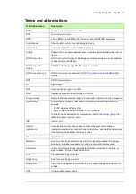
Page 11: ...ores electrical energy for example a battery or a super capacitor Frame size Refers to power modules that share a similar mechanical construction for example DC DC modules of frame R8i frame 2 R8i includes two size R8i DC DC modules To determine the frame size of a component refer to the Ratings page 104 tables in chapter Technical data INU Inverter unit Inverter Converts direct current and voltag...

Page 12: ...12 Introduction to the manual ...

Page 13: ...n principle and hardware description 13 2 Operation principle and hardware description Contents of this chapter This chapter describes the DC DC converter operation basics and the hardware of the converter unit ...

Page 14: ...DC converter modules must have a common energy storage Each parallel module must have the output cabling of its own We also recommend that you use identical cablings cable type cross sectional area and length and have identical load for each module For other solutions contact ABB Typically the DC DC converter is used in marine applications for heave compensation peak load compensation propulsion s...

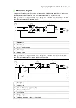
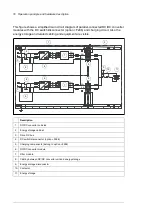
Page 15: ...ut the DC switch disconnector and charging circuit This figure shows a simplified main circuit diagram of a DC DC converter with the DC switch disconnector option F286 and charging circuit Description 1 Drive DC bus 2 DC DC converter module 3 Filter module 4 Energy storage Description 1 Drive DC bus 2 DC switch disconnector option F286 3 DC DC converter module 4 Filter module 5 Energy storage 6 Ch...

Page 16: ...storage and related cabling and equipment are visible Description 1 DC DC converter cubicles 2 Energy storage cabinet 3 Drive DC bus 4 DC switch disconnector option F286 5 Charging components belong to option F286 6 DC DC converter module 7 Filter module 8 Cabling between DC DC converter unit and energy storage 9 Energy storage disconnector 10 Contactor 11 Energy storage 6 6 6 6 6 6 6 6 6 6 1 2 3 ...

Page 17: ... the storage from the DC DC converter The disconnecting device does not belong to the ACS880 1607 unit delivery Description 1 AC supply 2 Input AC fuses 3 Supply module 4 DC bus 5 Inverter DC fuses with or without a DC switch disconnector option F286 6 Inverter modules 7 Motors 8 DC fuses DC bus side with or without a DC switch disconnector option F286 9 DC DC converter unit converter and filter m...

Page 18: ...n F286 but commonly used A converter unit with a DC switch disconnector also has a precharge circuit including a charging switch on the door The figures show the components of the converter unit cubicle with the door closed and with the door open and shrouds removed In this figure the DC DC converter unit cubicle has the DC switch disconnector and charging circuit Door closed Door open 1 2 3 3 4 6...

Page 19: ...stors R1 x R4 x are behind the charging controller 10 Charging switch Q10 1 shaft 11 X33 1 Connection from the energy storage disconnecting device to the load disconnected indicator P13 x 12 T22 1 24 V DC power supply 13 Q26 1 Contactor for filter fan control 14 Control panel 15 P11 1 P13 1 Door lights Charging OK P11 x green DC DC converter disconnected P12 x white Load disconnected P13 x white F...

Page 20: ...ption F286 and charging circuit Design Description 1 T11 1 R8i DC DC converter module 2 R13 1 Filter module 3 Module cooling fans 4 Lead throughs for energy storage cables 5 ES ES Energy storage connection 6 A41 Control unit Door closed Door open 1 2 3 3 4 6 7 12 Without DC switch disconnector and charging 5 8 9 10 11 9 10 11 ...

Page 21: ...3 1 Connection from the energy storage disconnecting device to the load disconnected indicator P13 x 10 T22 1 24 V DC power supply 11 Q26 1 Contactor for filter fan control 12 P13 1 Door light Load disconnected P13 x white For more information see DC DC converter control devices on page 25 Design Description ...

Page 22: ...connection 2 Handle 3 Fiber optic connectors of the module wired to the control unit 4 Fan 5 Quick connector BDCL connection The counterpart fastened to the cabinet behind the module 6 Wheels 7 Type designation label of the module 8 Terminal block X50 power supply for internal boards and module heating element option C183 DOL fan supply option C188 9 Connector X53 For more information on the conne...

Page 23: ...nt Description A Filter module front B Filter module back 1 Energy storage connection 2 Converter module connection 3 Terminal block X55 DOL fan supply option C188 ready connected 4 Handle 5 Fan 6 Wheels 7 Terminal block X30 module DOL fan supply option C188 8 Type designation label of the module 9 The unpainted grounding point 10 Lifting eyes A 6 2 4 1 3 5 7 8 9 B 10 ...

Page 24: ...e diagram shows the control connections and interfaces of the BCU control unit No Description No Description 1 2 3 Analog and digital I O extension modules and fieldbus communication modules can be inserted into slots 1 2 and 3 7 Control panel or PC 4 Memory unit 8 Fiber optic links to the converter modules 5 Slot 4 for RDCO 0x 9 Ethernet interface 6 Terminal blocks See chapter Control unit on pag...

Page 25: ...rging circuit WARNING You must also switch off the charging switch to disconnect the DC DC converter from the DC supply Do not operate the DC switch disconnector under load Charging switch A converter unit with a DC switch disconnector Q11 option F286 also has charging circuit and a charging switch Q10 x on the cubicle door Before closing the DC switch disconnector close the charging switch After ...

Page 26: ...p the converter unit view and reset the fault and warning messages and view the fault history view actual signals change parameter settings change between local and external control The control panel can be mounted on the cabinet door using a DPMP 01 mounting platform available separately For the instructions on the use of the panel see ACX AP x assistant control panels user s manual 3AUA000008568...

Page 27: ...verter unit on page 30 2 Frame size 3 Cooling system and other additional data 4 Degree of protection 5 Ratings See also section Ratings on page 104 Input power DC bus connection on page 112 and Output power energy storage connection on page 112 6 Valid markings See Electrical planning instructions for ACS880 multidrive cabinets and modules 3AUA0000102324 English 7 Serial number The first digit of...

Page 28: ...e 3 Degree of protection 4 UL CSA data See section Input power DC bus connection on page 112 5 Ratings See also section Ratings on page 104 Input power DC bus connection on page 112 and Output power energy storage connection on page 112 6 Valid markings See Electrical planning instructions for ACS880 multidrive cabinets and modules 3AUA0000102324 English 7 Serial number The first digit of the seri...

Page 29: ...n page 32 2 Degree of protection 3 UL CSA data 4 Ratings 5 Code of the filter 6 Valid markings See Electrical planning instructions for ACS880 multidrive cabinets and modules 3AUA0000102324 English 7 Serial number The first digit of the serial number refers to the manufacturing plant The next four digits refer to the unit s manufacturing year and week respectively The remaining digits complete the...

Page 30: ...documentation in English in memory stick Size 0900A Refer to the rating tables on page 104 Voltage range 3 DC voltage corresponding AC input voltages 3 380 415 V This is indicated in the type designation label as typical input voltage level 566 V DC 5 DC voltage corresponding AC input voltages 3 380 500 V This is indicated in the type designation label as typical input voltage levels 566 679 707 V...

Page 31: ...A 01 PROFIBUS DP DPV0 DPV1 K457 FieldBus1 FCAN 01 CANopen K458 FieldBus1 FSCA 01 Modbus RTU K462 FieldBus1 FCNA 01 ControlNet K469 FieldBus1 FECA 01 EtherCAT K470 FieldBus1 FEPL 02 Ether POWERLINK K473 FieldBus1 FENA 011 EtherNet IP Modbus TCP PROFINET K475 FieldBus1 FENA 21 EtherNet IP Modbus TCP PROFINET IO Daisy chain K480 Ethernet switch Ethernet switch for PC tool and control network K483 Eth...

Page 32: ...verter module The module delivery includes a speed controlled cooling fan as standard Size 600A Refer to the rating tables on page 104 Voltage range 3 DC voltage corresponding AC input voltages 3 380 415 V This is indicated in the type designation label as typical input voltage level 566 V DC 5 DC voltage corresponding AC input voltages 3 380 500 V This is indicated in the type designation label a...

Page 33: ... mechanical installation of the converter units DC DC converter units For checking the installation site moving the unit and installing cabinets see Mechanical installation instructions for ACS880 multidrive cabinets 3AUA0000101764 English Energy storage Obey the energy storage manufacturer s instructions ...

Page 34: ...34 Mechanical installation ...

Page 35: ...e local laws and regulations ABB does not assume any liability whatsoever for any installation which breaches the local laws and or other regulations Furthermore if the recommendations given by ABB are not followed the drive may experience problems that the warranty does not cover Generic guidelines See Electrical planning instructions for ACS880 multidrive cabinets and modules 3AUA0000102324 Engl...

Page 36: ...s ACS880 207 typically with regenerative rectifier units ACS880 907 where We recommend to measure the energy storage voltage If you use a super capacitor as the energy storage voltage measurement is obligatory If the converter is equipped with the BAMU voltage current measurement unit option G442 the converter measures its output voltage and thus also the ES voltage automatically You do not need a...

Page 37: ...arging device Connect the load disconnected indicator P13 x to the disconnecting device of the energy storage See Connecting the energy storage cable and load disconnected indicator cable on page 47 Make sure that the user cannot close the energy storage disconnector before the DC switch disconnector Q11 xx option F286 of the DC DC converter is closed Equip the system with appropriate interlocking...

Page 38: ...Cable data 3 conductor cable 4 conductor cable PVC T 70 C copper cable XLPE T 90 C copper cable PVC T 70 C copper cable XLPE T 90 C copper cable mm2 mm2 mm2 mm2 UN 400 V ACS880 1607 0600A 3 R8i 720 3 3 185 95 2 3 240 120 2 4 120 70 1 4 240 120 ACS880 1607 0900A 3 R8i 1080 4 3 240 120 4 3 150 70 2 4 240 120 2 4 185 95 ACS880 1607 1200A 3 2 R8i 1440 2 3 3 185 95 2 2 3 240 120 4 4 120 70 2 4 240 120 ...

Page 39: ... IGBT semiconductors The longer the cable the higher the radiated emissions inductive load and voltage peaks over the IGBTs of the DC DC converter Maximum cable length The maximum cable length of the energy storage cable s is 100 m 328 ft EMC compliance of the complete installation Note ABB has not verified that the EMC requirements are fulfilled with external energy storage and its cabling The EM...

Page 40: ...40 Guidelines for planning electrical installation ...

Page 41: ...er contains instructions on wiring the converter units Note The instructions do not cover electrical installation of the energy storage media Safety WARNING Obey the safety instructions for the drive See Safety instructions for ACS880 multidrive cabinets and modules 3AUA0000102301 English ...

Page 42: ...rive whichever is present Open the disconnector of the supply transformer as the main disconnecting device of the drive does not remove the voltage from the input busbars of the drive or from the voltmeter option G334 if present Make sure that reconnection is not possible Lock the disconnectors to open position and attach a warning notice to them Disconnect any external power sources from the cont...

Page 43: ...ARNING Open the DC switch disconnector Q11 option F286 of each DC DC converter Do not make any voltage tolerance or insulation resistance tests on the converter modules Every converter module has been tested for insulation between the main circuit and the chassis at the factory Check the insulation resistance of the energy storage as instructed by its manufacturer Check the energy storage cable as...

Page 44: ...abinet lead through below 4 Route the control cables to the control connection terminals Use the existing trunking in the cabinet wherever possible Use sleeving if cables are laid against sharp edges 5 Connect the control cables See chapter Control unit and the circuit diagrams delivered with the drive 6 Refit any shrouds removed earlier and close the door of the cubicle Grounding the outer shield...

Page 45: ...ommet sufficient IP and EMC protection can be achieved However if very many control cables come to one cabinet plan the installation beforehand as follows 1 Make a list of the cables coming to the cabinet 2 Sort the cables going to the left into one group and the cables going to the right into another group to avoid unnecessary crossing of cables inside the cabinet 3 Sort the cables in each group ...

Page 46: ...rrange the bunches according to size from thickest to the thinnest between the EMI conductive cushions 6 If more than one cable go through a grommet seal the grommet by applying Loctite 5221 catalogue number 25551 inside the grommet ...

Page 47: ...the cable lead through If you use parallel cables make sure they are identical type cross sectional area length etc 2 Disconnector 3 Connection to the load disconnected indicator P13 x on the cabinet door See Selecting the energy storage on page 36 4 Shielded 4 conductor cable and 360 degree grounding of the cable shield at the cable lead through If you use parallel cables make sure they are ident...

Page 48: ...onverter cubicle and remove the shrouding 3 Lead the cables into the cubicle 4 Ground the cable shield 360 degrees at the cable entry See the instructions by the cabinet installer An example grounding arrangement is shown below 5 Cut the cables to suitable length Strip the cables and conductors and install the cable lugs at the end of the conductors 6 Twist the cable screens into bundles and conne...

Page 49: ...ve the shrouding 3 Run the load disconnected indicator cable into the cubicle as described in section Grounding the outer shields of the control cables at the cabinet lead through on page 44 4 Make a 360 grounding of the cable shield at the cable lead through See Grounding the outer shields of the control cables at the cabinet lead through on page 44 5 Route the cable to terminal block X33 1 termi...

Page 50: ...teps described in section Electrical safety precautions on page 42 2 Ensure by measuring that the I O terminals of the control unit especially the relay output terminals are safe 3 Insert the module carefully into its slot on the control unit 4 Fasten the module For instructions see the documentation of the module 5 Connect the necessary wiring to the module following the instructions given in the...

Page 51: ... PC directly to the control panel connector of the DC DC converter unit as this can cause damage 2 Remove the USB connector cover on the front of the control panel 3 Connect an USB cable Type A to Type Mini B between the USB connector on the control panel and a free USB port on the PC 4 The panel displays an indication whenever the connection is active 5 See the documentation of the PC tool for se...

Page 52: ...52 Electrical installation ...

Page 53: ...rol unit consists of a BCON control board and a BIOC I O and power supply board built in a metal housing The BCU is mounted separately from the converter module s and connected to the module s by fiber optic cables In this manual the name BCU represents the control unit types BCU 02 BCU 12 and BCU 22 These have a different number of converter module connections 2 7 and 12 respectively but are othe...

Page 54: ...ot in use by default 3 DI3 4 DI4 5 DI5 6 DI6 7 DIIL XDIO Digital input outputs 1 DIO1 Not in use by default 2 DIO2 Not in use by default 3 DIOGND Digital input output ground 4 DIOGND Digital input output ground XD24 Auxiliary voltage output 5 24VD 24 V DC 200 mA 6 6 DICOM Digital input ground 7 24VD 24 V DC 200 mA 6 8 DIOGND Digital input output ground DICOM DIOGND Ground selection switch 7 XAI An...

Page 55: ... the drive to drive D2D link 6 Total load capacity of these outputs is 4 8 W 200 mA at 24 V minus the power taken by DIO1 and DIO2 7 Determines whether DICOM is separated from DIOGND ie common reference for digital inputs floats DICOM DIOGND ON DICOM connected to DIOGND OFF DICOM and DIOGND separate 8 The Safe torque off STO function is only implemented in the inverter units When the control board...

Page 56: ... AI1 I current U voltage AI2 Mode selector for analog input AI2 I current U voltage D2D TERM Termination switch for drive to drive link D2D DICOM DIOGND Ground selection Determines whether DICOM is separated from DIOGND ie the common reference for the digital inputs floats 7 segment display Multicharacter indications are displayed as repeated sequences of characters U is indicated briefly before o...

Page 57: ...t in use in DC DC converter units X13 Control panel connection X485 Not in use V1T V1R V2T V2R Fiber optic connection to converter modules 1 and 2 VxT transmitter VxR receiver V3T V3R V7T V7R Fiber optic connection to converter modules 3 7 BCU 12 22 only VxT transmitter VxR receiver V8T V8R V12T V12R Fiber optic connection to converter modules 8 12 BCU 22 only VxT transmitter VxR receiver SD CARD ...

Page 58: ...g up to 8 ms Digital inputs outputs DIO1 and DIO2 XDIO 1 and XDIO 2 Input output mode selection by parameters DIO1 can be configured as a frequency input 0 16 kHz with hardware filtering of 4 microseconds for 24 V level square wave signal sinusoidal or other wave form cannot be used DIO2 can be configured as a 24 V level square wave frequency output See the firmware manual of the converter unit pa...

Page 59: ...nel per module Note Safe torque off STO functionality is not available in the DC DC converter units See Default I O connection diagram on page 54 EMC immunity according to IEC 61326 3 1 Safe torque off output XSTO OUT Connector pitch 5 mm wire size 2 5 mm2 Output for powering XSTO inputs See Default I O connection diagram on page 54 Control panel connection X13 Connector RJ 45 Cable length 3 m Eth...

Page 60: ...IO DIO1 1 DIO2 2 DIOGND 3 DIOGND 4 XDI DI1 1 DI2 2 DI3 3 DI4 4 DI5 5 DI6 6 DIIL 7 XSTO OUT 1 SGND 2 IN1 3 IN2 4 XSTO OUT IN1 5 SGND 6 IN2 7 SGND 8 Ground Common mode voltage between each AI input and AGND is 30 V Ground selector DICOM DIOGND settings DICOM DIOGND ON All digital inputs share a common ground DICOM connected to DIOGND This is the default setting DICOM DIOGND OFF Ground of digital inp...

Page 61: ...ete before you start up the converter Warnings WARNING Obey the safety instructions for the drive See Safety instructions for ACS880 multidrive cabinets and modules 3AUA0000102301 English If you ignore the safety instructions injury or death or damage to the equipment can occur Only a qualified electrician is allowed to work on the installation ...

Page 62: ...t Pull the conductors to check Proper grounding has also been measured according to the regulations The energy storage has been equipped with fuses for protecting the energy storage cable in a cable short circuit situation The energy storage has been equipped with a disconnecting device The load disconnected indicator cable has been connected to the correct terminals of DC DC converter and to the ...

Page 63: ... These instructions do not cover all possible start up tasks of a customized drive and energy storage media Always refer to the delivery specific circuit diagrams when proceeding with the start up WARNING Only qualified by ABB electricians engineers are allowed to do the work described in this chapter In addition the electrician engineer must know the energy storage system he is about to take in u...

Page 64: ... device Make sure that the mechanical and electrical installation of the converter unit has been inspected and is OK See chapter Installation checklist Make sure that the drive is ready for the converter unit start up The supply and inverter units have been installed according to the instructions given in their hardware manuals The supply unit has been started up according to the instructions give...

Page 65: ...ly unit 2 Close the DC DC converter charging switch Q10 x The DC DC converter disconnected indicator P12 x goes out 3 After the Charging OK indicator P11 x illuminates close the DC switch disconnector Q11 4 Open the DC DC converter charging switch Q10 x Note The charging switch must be open before you can start the DC DC converter DC DC converter without DC switch disconnector no option F286 1 Clo...

Page 66: ...erter control program firmware manual 3AXD50000024671 English Disconnecting the energy storage Open the contactor of the energy storage Open the disconnector of the energy storage Lock out and tag out The load disconnected indicator P13 x is lit Disconnecting the DC DC converter Open the DC switch disconnector Q11 option F286 Lock out and tag out The DC DC converter disconnected indicator P12 x is...

Page 67: ...r working inside the DC DC converter cubicle close the cubicle door and obey the instructions of Connecting voltage to the drive and converter control unit Charging the DC DC converter and connecting voltage to the converter and Connecting the energy storage to the DC DC converter on page 65 Starting the DC DC converter Start the converter unit See DC DC converter control program firmware manual 3...

Page 68: ...68 Start up ...

Page 69: ...stalled ACS880 1607 DC DC converter units WARNING Only qualified electricians are allowed to do the work described in this chapter Read the complete safety instructions before you install commission use or service the converter The complete safety instructions are given in Safety instructions for ACS880 multidrive cabinets and modules 3AUA0000102301 English ...

Page 70: ...additional maintenance recommendations Maintenance task object Years from start up 0 1 2 3 4 5 6 7 8 9 10 11 12 Cooling fans Main cooling fan speed controlled R Main cooling fan direct on line 50 Hz R R Main cooling fan direct on line 60 Hz R R BDCL filter cooling fan DOL 50 Hz R R BDCL filter cooling fan DOL 60 Hz R R Cooling fan for circuit boards R R Cabinet cooling fan internal R R Cabinet coo...

Page 71: ...s maintenance timers and counters that can be configured to generate a warning when a pre defined limit is reached Each timer counter can be set to monitor any parameter This feature is especially useful as a service reminder For more information see the firmware manual ...

Page 72: ...se a vacuum cleaner with an antistatic hose and nozzle and wear a grounding wristband Otherwise an electrostatic charge might build up and damage the circuit boards 1 Disconnect the drive from the AC power line and DC DC converter from the energy storage and obey the instructions in section Electrical safety precautions on page 42 See Disconnecting the DC DC converter with DC switch disconnector o...

Page 73: ...inlet meshes If the dust cannot be removed by vacuum cleaning from outside through the grating holes with a small nozzle proceed as follows 1 Recommendation De energize the fans by switching off the DC DC converter unit Obey the instructions in section Electrical safety precautions on page 42 2 Remove the fasteners at the top of the grating 3 Lift the grating and pull it away from the door 4 Vacuu...

Page 74: ...ecautions on page 42 2 Remove the fasteners at the top of the grating 3 Lift the grating and pull it away from the door 4 Remove the air filter mat 5 Place the new filter mat in the grating the metal wire side facing the door 6 Reinstall the grating in reverse order Cleaning the outlet roof filters IP54 The outlet roof filter in IP54 units can be accessed by pulling the grating upwards 2 3 4 5 6 ...

Page 75: ... drive If you ignore them injury or death or damage to the equipment can occur 1 Disconnect the drive from the AC power line and DC DC converter from the energy storage and obey the instructions in section Electrical safety precautions on page 42 See Disconnecting the DC DC converter with DC switch disconnector option F286 on page 66 2 Check the tightness of the cable connections Use the tightenin...

Page 76: ...s given in Safety instructions for ACS880 multidrive cabinets and modules 3AUA0000102301 English before you service the drive If you ignore them injury or death or damage to the equipment can occur Replace a blown fuse with a new one of the same type as follows For tables of recommended fuses see DC fuses DC bus side on page 107 and Output DC fuses energy storage side on page 107 1 Disconnect the ...

Page 77: ... order of the washers on the screws 5 Remove the screws nuts and washers from the old fuses and attach them to the new fuses Make sure to keep the washers in the original order 6 Insert the new fuses into their slots in the cubicle 7 Tighten the nuts to torque as follows Bussmann fuses 50 N m 37 lbf ft Other Refer to the fuse manufacturer s instructions 8 Reinstall the shroud in reverse order to t...

Page 78: ...301 English before you service the drive If you ignore them injury or death or damage to the equipment can occur WARNING Wear protective gloves and long sleeves Some parts have sharp edges 1 Disconnect the drive from the AC power line and DC DC converter from the energy storage and obey the instructions in section Electrical safety precautions on page 42 See Disconnecting the DC DC converter with ...

Page 79: ...m injury or death or damage to the equipment can occur WARNING Wear protective gloves and long sleeves Some parts have sharp edges 1 Disconnect the drive from the AC power line and DC DC converter from the energy storage and obey the instructions in section Electrical safety precautions on page 42 See Disconnecting the DC DC converter with DC switch disconnector option F286 on page 66 2 Open the d...

Page 80: ...80 Maintenance 7 3 4 5 6 ...

Page 81: ...amage to the equipment can occur WARNING Wear protective gloves and long sleeves Some parts have sharp edges 1 Disconnect the drive from the AC power line and DC DC converter from the energy storage and obey the instructions in section Electrical safety precautions on page 42 See Disconnecting the DC DC converter with DC switch disconnector option F286 on page 66 2 Open the door 3 Remove the cover...

Page 82: ...82 Maintenance 3 4 5 6 7 8 9 9 ...

Page 83: ...AUA0000102301 English before you service the drive If you ignore them injury or death or damage to the equipment can occur WARNING Wear protective gloves and long sleeves Some parts have sharp edges 1 Disconnect the drive from the AC power line and DC DC converter from the energy storage and obey the instructions in section Electrical safety precautions on page 42 See Disconnecting the DC DC conve...

Page 84: ...rom the fan holder 8 Put the new fan onto the threaded studs on the fan holder with the airflow direction arrow pointing towards the fan holder 9 Install and tighten the four nuts removed earlier 10 Connect the fan cable 11 Align and push the fan holder into the module 7 6 9 8 ...

Page 85: ...Maintenance 85 12 Install and tighten the two screws 10 11 12 ...

Page 86: ... damage to the equipment can occur WARNING Wear protective gloves and long sleeves Some parts have sharp edges 1 Disconnect the drive from the AC power line and DC DC converter from the energy storage and obey the instructions in section Electrical safety precautions on page 42 See Disconnecting the DC DC converter with DC switch disconnector option F286 on page 66 2 Open the door 3 Remove the scr...

Page 87: ...otective gloves and long sleeves Some parts have sharp edges 1 Disconnect the drive from the AC power line and DC DC converter from the energy storage and obey the instructions in section Electrical safety precautions on page 42 See Disconnecting the DC DC converter with DC switch disconnector option F286 on page 66 2 Remove all ventilation covers lift and pull and filters and finally remove the r...

Page 88: ... parts have sharp edges WARNING Use a vacuum cleaner with an antistatic hose and nozzle Using a normal vacuum cleaner creates static discharges which can damage circuit boards 1 Disconnect the drive from the AC power line and DC DC converter from the energy storage and obey the instructions in section Electrical safety precautions on page 42 See Disconnecting the DC DC converter with DC switch dis...

Page 89: ... ramp While pulling on the handle keep a constant pressure with one foot on the base of the module to prevent the module from falling on its back When replacing a module push the module up the ramp and back into the cubicle Keep your fingers away from the edge of the module front plate to avoid pinching them between the module and the cubicle Also keep a constant pressure with one foot on the base...

Page 90: ...erter and filter modules undo the screws that fasten the marine support to the modules a Loosen the screws that fasten the support to the corner posts do not remove the screws b Remove the support Note Reinstall the converter and filter module screws b before removing the modules from the cubicle 8 Remove the two screws that fasten the bottom of the module to the base of the cabinet 9 Install the ...

Page 91: ... falling on its back Note Be careful not to break the fastening screws tighten the fastening screws of the module to 22 N m 16 2 lbf ft and fastening bolts of the DC output busbars to 70 N m 51 6 lbf ft Plug the module signal wire set to the module terminal block X50 Reconnect the fiber optic cables Fasten the shrouds 13 Remove the module pull out ramp and close the cabinet doors ...

Page 92: ...92 Maintenance 3 6 4 5 4 7a 7b 7b ...

Page 93: ...Maintenance 93 9 8 8 10 11 ...

Page 94: ...ng the ramp While pulling on the handle keep a constant pressure with one foot on the base of the module to prevent the module from falling on its back When replacing a module push the module up the ramp and back into the cubicle Keep your fingers away from the edge of the module front plate to avoid pinching them between the module and the cubicle Also keep a constant pressure with one foot on th...

Page 95: ...e ramp s holes 8 Remove the two fastening screws that fasten the top of the module to the cabinet frame 9 Pull the module carefully out of the cabinet along the ramp While pulling on the handle keep a constant pressure with one foot on the base of the module to prevent the module from falling on its back 10 Replace the module install the module in reverse order Mind you fingers Keep a constant pre...

Page 96: ...96 Maintenance 4 8 6 7 5 3 ...

Page 97: ...Maintenance 97 9 ...

Page 98: ...act ABB if capacitor failure is suspected Replacements are available from ABB Do not use other than ABB specified spare parts Contact an ABB service representative for spare parts and repair services Reforming the capacitors The capacitors must be reformed if the drive has not been powered either in storage or unused for a year or more See section Type designation labels on page 27 for information...

Page 99: ...ockwise until the lid opens 2 Replace the battery with a new CR2032 battery 3 Put the lid back and tighten it by turning it clockwise 4 Dispose of the old battery according to local disposal rules or applicable laws Cleaning the control panel See ACX AP x assistant control panels user s manual 3AUA0000085685 English ...

Page 100: ...ry unit from the defective unit to the new unit WARNING Only qualified electricians are allowed to do this work Read the complete safety instructions of the drive If you ignore them injury or death or damage to the equipment can occur WARNING Do not remove or insert the memory unit when the control unit is powered 1 Disconnect the drive from the AC power line and DC DC converter from the energy st...

Page 101: ...nated when the control unit is powered For information on the LED see Layout and connections on page 56 1 Undo the fastening screw and remove the battery 2 Replace the battery with a new BR2032 battery 3 Dispose the old battery according to local disposal rules or applicable laws 4 Set the real time clock ...

Page 102: ... unit Continuous red There is an active fault in the DC DC converter unit Control panel mounting platform with the control panel removed Red There is an active fault in the DC DC converter unit Green Power supply for the control board of the DC DC converter unit is ok DC DC converter module FAULT continuous red There is an active fault in the DC DC converter module ENABLE STO continuous green The ...

Page 103: ...Technical data 103 10 Technical data Contents of this chapter This chapter contains the technical data for the DC DC converter units ...

Page 104: ...90 V 0400A 7 0410A 7 R8i 400 400 351 471 600 351 38 12000 0600A 7 0600A 7 R8i 600 600 527 707 900 527 56 12000 0800A 7 0410A 7 2 R8i 800 800 703 942 1200 703 19 24000 1200A 7 0600A 7 2 R8i 1200 1200 1054 1413 1800 1054 28 24000 3AXD00000601909 Unit type ACS880 1607 Consists of module type ACS880 104 Frame High overload use Heavy duty use Ifast Pfast IHd PHd A kW A kW UN 400 V 0600A 3 0640A 3 R8i 4...

Page 105: ...nals energy storage connection measured after the filter High overload use Ifast Continuous current allowing Imax for 10 s 60 s at 40 C 104 F Pfast Continuous power allowing Imax for 10 s 60 s at 40 C 104 F Heavy duty use IHd Continuous current allowing 150 IHd for 1 min 5 min at 40 C 104 F PHd Continuous power allowing 150 IHd for 1 min 5 min at 40 C 104 F Notes The ratings apply at an ambient te...

Page 106: ...e output current can be calculated by multiplying the current given in the rating table by the derating factor k Altitude derating At altitudes 0 1000 m 3300 ft no derating At altitudes from 1000 to 4000 m 3300 to 13123 ft above sea level the continuous output currents given above must be derated 1 for every 100 m 328 ft T 1 00 0 90 40 C 104 F 50 C 122 F k 0 80 ...

Page 107: ... type 170M6549 2 0800A 7 700 A 1250 V size 3 Flush end type 170M6545 4 1200A 7 1100 A 1000 V size 3 Flush end type 170M6549 4 3AXD00000601909 Unit type ACS880 1607 Rating Type Example Bussman Qty UN 400 V 0600A 3 1100 A 690 V size 3 Flush end type 170M6415 2 0900A 3 1600 A 690 V size 3 Flush end type 170M6419 2 1200A 3 1100 A 690 V size 3 Flush end type 170M6415 4 1800A 3 1600 A 690 V size 3 Flush...

Page 108: ... 0600A 3 1 R8i 1 BDCL 14 5 0900A 3 1 R8i 1 BDCL 15 5 1200A 3 2 R8i 2 BDCL 14 5 1800A 3 2 R8i 2 BDCL 15 5 UN 500 V 0600A 5 1 R8i 1 BDCL 14 5 0900A 5 1 R8i 1 BDCL 15 5 1200A 5 2 R8i 2 BDCL 14 5 1800A 5 2 R8i 2 BDCL 15 5 UN 690 V 0400A 7 1 R8i 1 BDCL 14 7 0600A 7 1 R8i 1 BDCL 15 7 0800A 7 2 R8i 2 BDCL 14 7 1200A 7 2 R8i 2 BDCL 15 7 3AXD00000601909 ...

Page 109: ...0A 3 2145 84 4 2315 91 1 1600 63 0 636 25 756 29 8 1360 2998 UN 500 V 0600A 5 2145 84 4 2315 91 1 800 31 5 636 25 756 29 8 650 1433 0900A 5 2145 84 4 2315 91 1 800 31 5 636 25 756 29 8 680 1499 1200A 5 2145 84 4 2315 91 1 1600 63 0 636 25 756 29 8 1300 2866 1800A 5 2145 84 4 2315 91 1 1600 63 0 636 25 756 29 8 1360 2998 UN 690 V 0400A 7 2145 84 4 2315 91 1 800 31 5 636 25 756 29 8 650 1433 0600A 7...

Page 110: ...UN 500 V 0600A 5 R8i 6 0 2200 1295 74 98 5 0900A 5 R8i 9 1 2200 1295 74 98 4 1200A 5 2 R8i 12 1 4400 2590 76 98 4 1800A 5 2 R8i 18 8 4400 2590 76 98 4 UN 690 V 0400A 7 R8i 6 4 2200 1295 74 98 2 0600A 7 R8i 10 6 2200 1295 74 98 0 0800A 7 2 R8i 12 8 4400 2590 76 98 2 1200A 7 2 R8i 21 5 4400 2590 76 98 0 3AXD00000601909 Definitions Ploss Heat dissipation Maximum total losses of the DC DC converter an...

Page 111: ... 8 8 M4 1 N m 9 lbf in Strength class 4 6 8 8 M5 4 N m 35 lbf in Strength class 8 8 M6 9 N m 6 6 lbf ft Strength class 8 8 M8 22 N m 16 lbf ft Strength class 8 8 M10 42 N m 31 lbf ft Strength class 8 8 M12 70 N m 52 lbf ft Strength class 8 8 M16 120 N m 90 lbf ft Strength class 8 8 Size Max torque Note M5 6 N m 53 lbf in Strength class 8 8 M6 10 N m 7 4 lbf ft Strength class 8 8 M8 24 N m 17 7 lbf...

Page 112: ...age 150 V 80 of UDC ACS880 104 xxxxx 5 Maximum output voltage 50 V 95 of UDC Drive DC voltage in the DC bus This is indicated in the type designation label as typical output voltage range 50 509 611 636 V DC Recommended output voltage 150 V 80 of UDC ACS880 104 xxxxx 7 Maximum output voltage 50 V 95 of UDC Drive DC voltage in the DC bus This is indicated in the type designation label as typical ou...

Page 113: ...rectly related to the actual communication speed Note The optical components transmitter and receiver on a fiber optic link must be of the same type Plastic optical fiber POF cables can be used with both 5 MBd and 10 MBd optical components 10 MBd components also enable the use of Hard Clad Silica HCS cables which allow longer connection distances thanks to their lower attenuation HCS cables cannot...

Page 114: ... severities Stationary use of weather protected locations IEC 60721 3 1 IEC 60721 3 2 Chemical gases Class 3C2 Class 1C2 Class 2C2 Solid particles Class 3S1 Class 1S3 packing must support this otherwise 1S2 Class 2S2 No conductive dust allowed Vibration IEC EN 61800 5 1 IEC 60068 2 6 2007 EN 60068 2 6 2008 Environmental testing Part 2 Tests Test Fc Vibration sinusoidal IEC EN 60721 3 3 2002 10 57 ...

Page 115: ...e exposed to corrosive atmosphere during transport or storage Container package timber VCI sheet film PE thickness 0 10 mm VCI stretch film PE thickness 0 04 mm VCI emitter bags PP tape PET strap sheet metal steel for sea transport in containers recommended for land and air transport when storage time prior to installation exceeds 6 months or storage is arranged in partially weather protected cond...

Page 116: ...vide and continuously ensure a secure connection between the product and Customer network or any other network as the case may be The Customer shall establish and maintain any appropriate measures such as but not limited to the installation of firewalls application of authentication measures encryption of data installation of anti virus programs etc to protect the product the network its system an...

Page 117: ...ions 117 11 Dimensions What this chapter contains This chapter contains the following dimension data Dimension drawings of DC DC converter unit Location and size of output terminals for energy storage cables ...

Page 118: ...118 Dimensions Dimension drawings Frame 1 R8i bottom cable entry ...

Page 119: ...Dimensions 119 Frame 1 R8i top cable entry ...

Page 120: ...120 Dimensions Location and size of input terminals Frame 1 R8i bottom cable entry Frame 1 R8i top cable entry ...

Page 121: ...ntacts can be found by navigating to www abb com searchchannels Product training For information on ABB product training navigate to new abb com service training Providing feedback on ABB Drives manuals Your comments on our manuals are welcome Navigate to new abb com drives manuals feedback form Document library on the Internet You can find manuals and other product documents in PDF format on the ...

Page 122: ...www abb com drives www abb com drivespartners 3AXD50000023644 Rev B EN 2017 01 30 Contact us ...

Reviews: