


Advance AutoQuip
2 McDonald Crescent | Bassendean WA 6054
Ph: 08 9279 1663 | Fax: 08 9279 1667 | E: [email protected] | W: www.aaq.net.au
- READ THE ENTIRE CONTENTS OF THIS MANUAL BEFORE
INSTALLATION AND OPERATION. BY PROCEEDING YOU AGREE THAT
YOU FULLY UNDERSTAND AND COMPREHEND THE FULL CONTENTS
OF THIS MANUAL. FORWARD THIS MANUAL TO ALL OPERATORS.
FAILURE TO OPERATE THIS EQUIPMENT AS DIRECTED MAY CAUSE
INJURY OR DEATH.
Specifications subject to change without notice.
Note: While all due care and attention has been taken in the preparation of this document, Advance AutoQuip shall not be liable for any inaccuracies or omissions
which may occur therein
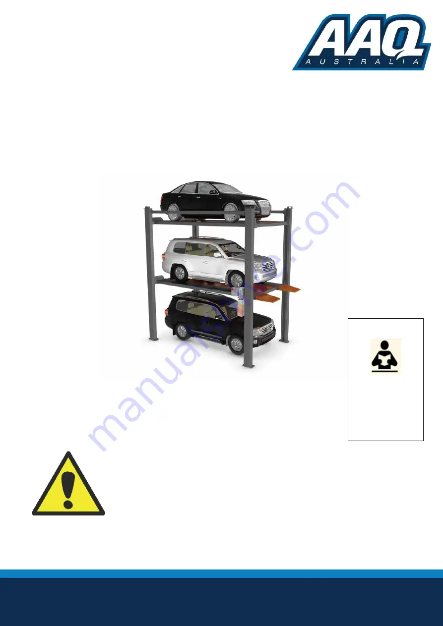
4 POST CAR STACKER
AutoLift
AL-
2525
Model No:
HP-2525 / HP-
2625
Four Post,
Three
Car Stacker
2500
Kg
Capacity Lower Platform, 2000Kg Capacity Upper Platform
Design Registration Approval Number:
N/A Domestic Application
Design Code: AS1418.9-1996
INSTALLATION MANUAL & OPERATION
INSTRUCTIONS
READ FIRST
DO NOT use the
machine until you read
and understand all the
dangers, warnings and
cautions in this manual.


